
Summary of Contents for Heatcraft Refrigeration Products HCS
- Page 1 Bulletin AH-TB January 2011 (Replaces AH-91C) Air Handlers Tech Bulletin For Air Conditioning, Heating and Ventilation Available in Bohn™, Climate Control™, Chandler™ & Larkin™ Models HCS, HCL VCS, HD Size 03 thru 75...
- Page 2 Our highest design priorities are for units with low operating costs, rugged construction, and the features most needed for simple trouble free installation and maintenance. Heatcraft Refrigeration Products' ISO 9000 certification guarantees consistent quality products for you and your customers. 3 - 10...
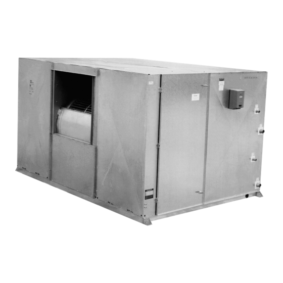
- Page 3 Cabinet style HCS — (S for Short) Insulated fan section with motor base and access door(s), horizontally adjacent (same elevation) with insulated short depth coil section with drain pan. HCL — (L for Long) Insulated fan section with motor base and access door(s), horizontally adjacent (same elevation) with insulated long coil section with drain pan.
- Page 4 All coil sections accommodate either small or large face area coils. The HCS coil section will hold 15 1/2" of coils and spacers. The HCS section covers most applications. Use the HCL coil section if the coil or access space is more than 15 1/2". (See page 38 for maximum per model.)
- Page 5 There are a wide variety of coil types to meet the load requirements of conditioned spaces. Heatcraft’s four coil types are: water, direct expansion, heat reclaim and steam coils. All standard coils have copper tubes and aluminum fins and a heavy gauge mill galvanized steel casing.
- Page 6 Accessories- Electric Heat lectric heaters are UL listed for duct installation. The UL label applies to the heater only, not the complete air handler. Heaters are furnished as a separate section and are available with insulated or uninsulated casings. Controls such as contactors, fuses, etc., may be factory installed and wired in the heater section end panel provided the number of control steps is not excessive.
- Page 7 The standard electric heater section construction includes: Automatic thermal cutout Heat limiters Air flow switch Maximum KW per contactor and per fuse block (at least one contactor is required per step of heating): Electric Heater Selection Example How many KW is needed to increase temperature of 17000 CFM by 27 °F for Air Handler Model Size 34? 17000 X 27 3000 How many steps required at 10°F rise per step?
- Page 8 Accessories Flat Filter Sections Flat filter sections are space saving and economical. Choose either two inch or four inch filters. The two inch filters can be the throwaway, the 35% pleated, or the high velocity cleanable type. Four inch filters are 35% pleated, they have more filter surface than two inch filters.
- Page 9 • Mixbox section, without dampers, with top, bottom, or back inlet openings, • HCS type coil module, includes insulation, drain pan and four mounting legs, 15.5" max coil depth, see page 38. • HCL type coil module, includes insulation, drain pan and four mounting legs, and more coil depth, see page 38.
- Page 10 Coil Section Accessory: Large face area and small face area coils (see pages 42 & 43) ...All HCS, HCL, HD, and VCS coil cabinets Balancing dampers above small coil (to adjust air flow over coil in the field) ...All HCS, HCL, HD, and VCS cabinets Blank off plate above small sized coil (to force entire air flow over coil) ...All HCS, HCL, HD, and VCS cabinets...
- Page 11 Air handler selections vary with each application. Use the index below to find Heatcraft Products air handler performance tables for: • Standard comfort cooling (either direct expansion or chilled water) • Heating (either steam or hot water, either make up air or return air) •...
- Page 12 85.8 GPM and 13.5 feet of fluid pressure drop 502 MBH of heating capacity with 60°F. entering air and 200°F. entering water at 64.5 gpm and 12.3 feet of fluid pressure drop inches inches inches fits into HCS type cabinet Performance:...
- Page 13 Air Handler Performance - Quick Reference Table 1 Heating and Cooling Performance for Selected Coils See notes for coil descriptions and rating conditions. Note 1 Note 2 air volume at air handler Unit 500 fpm 2.54 m/s face area Size cu m/h SQ FT sq m...
- Page 14 Air Handler Performance- Direct Expansion Table 2 Comfort Cooling 1/2" tube, entering air at 80°F. DB and 67°F. WB** Coil Unit Face 35°F. SST Size Area Total Sens. 1565 3.13 2880 5.76 3905 7.81 4885 9.77 6200 12.40 7290 14.58 8855 17.71 10025...
- Page 15 Air Handler Perfromance- Direct Expansion Table 4 Supermarket Air Conditioning 1/2" tube, entering air at 75°F. DB and 63°F. WB** Coil Unit Face 35°F. SST Size Area Total Sens. 1565 3.13 2880 5.76 3905 7.81 4885 9.77 6200 12.40 7290 14.58 8855 17.71...
- Page 16 Air Handler Performance- Chilled Water Table 6 Comfort Cooling Coil 42°F. Entering Water Unit Face Size Area TOTAL SENS 1565 3.13 2880 5.76 3905 7.81 4885 9.77 6200 12.40 7290 14.58 8855 17.71 10025 20.05 13280 26.56 16825 33.65 20365 40.73 25313 50.63...
- Page 17 Air Handler Perfromance- Chilled Water Table 8 Comfort Cooling Coil 42°F. Entering Water Unit Face Size Area TOTAL SENS 1565 3.13 2880 5.76 3905 7.81 4885 9.77 6200 12.40 7290 14.58 8855 17.71 10025 20.05 13280 26.56 16825 33.65 20365 40.73 25313 50.63...
- Page 18 Air Handler Performance- Hot Water/Steam Table 10 Heating, Water Face 180°F. Entering Water Coils Unit Area One Row Size Sq. Ft. 1565 3.13 2880 5.76 14.8 3905 7.81 19.9 4885 9.77 25.3 6200 12.40 32.3 7290 14.58 38.4 8855 17.71 46.6 10025 20.05...
- Page 19 Air Handler Performance- Hot Water/Steam Table 12 Heating, Water Face 180°F. Entering Water Coils Unit Area One Row Size Sq. Ft. 1565 3.13 2880 5.76 3905 7.81 12.2 4885 9.77 15.7 6200 12.40 20.1 7290 14.58 24.0 8855 17.71 29.2 10025 20.05 33.7...
- Page 20 Coil Perfromance- Heat Reclaim MBH/SQ FT Heat Reclaim Coil Selection Example: Select reclaim coil for Size 26 air handler at 13280 CFM, 344 MBH reclaimed at 45°F. Temperature Difference. Change the application’s requirement at application’s TD to adjusted requirement at 50°F. TD. Use Table 15: 344/0.9 = 382.2 MBH (adjusted) Divide the adjusted MBH by the coil face area: 382.2 / 26.56 = 14.4 MBH (adjusted) per square foot...
- Page 21 Coil Performance- Direct Expansion MBH/SQ FT Table 17 Wet Evaporator Capacity 1/2" and 5/8" tube, entering air 80°F. DB, 67°F. WB Type A and Type 5, direct expansion at 40ºF. evaporating, cooling capacities MBH per SQ FT of coil face area FPM, Type A Coils (1/2"...
- Page 22 Coil Perfromance- Chilled Water MBH/SQ FT Table 19 1/2" and 5/8" tube, entering air 80°F. DB, 67°F. WB Chilled Type A and Type 5, chilled water at 45°F., cooling capacities Water MBH per SQ FT of coil face area (Max. water veocity= 3 fps) FPM, Type A Coils (1/2"...
- Page 23 Coil Performance- Heating, Water & Steam Table 21 Hot Water Type A and Type 5, 190°F. average water temperature MBH per SQ FT of coil face area (water velocity=3 fps). FPM, Type A Coils (1/2" DIA.) Rows 11.2 12.7 14.0 14.2 16.0 17.6...
- Page 24 Fan Performance Coil Std. Vel. 0.50 1.00 1200 0.23 1141 0.40 1300 0.26 1149 0.44 1400 0.29 1159 0.49 1500 0.33 1172 0.54 1600 0.37 1185 0.59 1700 0.41 1119 0.64 1800 0.47 1214 0.70 1900 0.52 1229 0.76 2000 0.59 1243 0.83...
- Page 25 Coil Std. Vel. 0.50 1.00 2700 0.47 0.80 3000 0.56 0.93 3300 0.69 1.06 3600 0.82 1.20 3900 0.98 1.37 4200 1.18 1.56 4500 1.41 1.80 4800 1.67 2.07 5100 1.97 2.33 5400 2.31 2.65 5700 2.69 3.01 6000 3.11 3.42 6300 3.57...
- Page 26 Fan Performance Coil Std. Vel. 0.50 1.00 4400 0.97 1.38 4800 1.18 1.60 5200 1.44 1.87 5600 1.74 2.18 6000 2.08 2.53 6400 2.45 2.92 6800 2.87 3.35 7200 3.33 3.85 7600 3.83 4.44 8000 4.38 5.06 8400 4.99 5.73 8800 5.64 6.46...
- Page 27 Coil Vel Std. Size Size 0.50 1.00 8500 — 1.66 9000 — 1.88 9500 — 2.10 10000 — 2.35 10500 2.63 11000 2.94 11500 3.27 12000 3.64 12500 4.04 13000 4.47 14000 5.44 15000 — 6.56 16000 — 7.84 17000 —...
- Page 28 Fan Performance Coil Std. Vel. 0.50 1.00 17000 3.07 4.81 18000 3.43 5.28 19000 3.87 5.77 20000 4.31 6.28 21000 4.80 6.83 22000 5.34 7.40 23000 5.92 8.01 24000 6.56 8.66 25000 7.24 9.36 26000 7.98 10.23 27000 8.78 11.06 28000 9.63 11.94...
- Page 29 Coil Vel Std. Size Size 0.50 23000 — 4.32 25500 — 5.48 28000 6.85 30500 8.44 33000 10.30 35500 12.40 38000 14.77 40500 17.48 43000 20.47 Coil Vel Std. Size Size 2.50 23000 — 12.04 25500 — 13.81 28000 15.78 30500 17.97 33000...
- Page 30 Accessory Flange Pattern Sizes 03 - 18 Dimensions Size 22 3/4 2 3/8 35 1/2 5 3/4 35 1/2 5 3/4 38 3/4 4 3/8 38 3/4 6 1/2 4 3/8 47 3/4 6 1/2 5 1/2 Flanges are 2", all sections. Mixbox Inlet Duct Connections All dimensions are in inches.
- Page 31 Unit air handler air handler air handler fan section Size width height depth height 49 1/2 28 11/16 —— 28 11/16 —— 73 1/2 35 1/2 —— 73 1/2 35 1/2 —— 38 3/4 —— 38 3/4 —— 38 3/4 38 3/4 Mix box Unit...
- Page 32 Note: For double wall construction and internal isolation, please consult factory * Add 6" to dim C if internal isolation and down discharge Models HCS and HCL Sizes 03 - 41 FC For electric heat, split the coil and the fan sections on sizes 03 through 18.
- Page 33 + Dimension “Q” is for Discharge Arrangement 2. For Discharge Arrangement 1, “Q” measures from corresponding side of unit. ^^ External face and bypass is available on HCL (long cabinet) models only. Note: For double wall construction and internal isolation, please consult factory Models HCS and HCL Sizes 50 - 75 AF fan discharge...
- Page 34 Dimensions Arrangements Available: 03 through 18 — Arrangements 1, 2, 3, 4. 5, 6.^^ Sizes 20 through 41 — Arrangements 1, 2, 3, 4.^^ Unit air handler air handler fan section fan discharge Size width height depth 25 1/4 22 3/4 10 1/4 28 1/2 13 7/16...
- Page 35 Notes: Motor and connection locations (R.H. or L.H.) determined when facing the front of the unit, with the air blowing through the coil and into observer’s face. Floor or platform mounting only. Ceiling suspension is not available. Electric Heat: See page 6 for heater section dimensions. Arrangements Available: Size 50 through 75 —...
- Page 36 84 1/4 106 5/8 115 3/4 109 1/4 —— 131 3/4 116 1/4 —— 131 3/4 —— Models HCS, HCL and VCS Sizes 03 - 75 Unit center to Size edge dimension 03 - 18 20 - 41 50 - 75...
- Page 37 Mounting Locations For Vibration Isolators l mounting holes are : 5/8 inch diameter. One and two row heating coils do not have support legs. air handler fan section fan section center Unit centers edge to centers to edge Size width edge depth depth dimension...
- Page 38 15 1/2 Accessory sections (All sizes): High capacity filter section Economizer section, combined with filters or without filters Access section Auxiliary coil section (either HCS or HCL ) Electric preheat section High efficiency filter section Models HCS - HCL - VCS...
- Page 39 High Efficiency - 44" Section Mixbox Other Accessory Internal Face and Bypass Sections External Face and Bypass Auxiliary Coil Module HCS Auxillary Coil Module HCL Electric Heater Large Type 5 Coils 10 FPI (Coil weights include the weight of water when filled)
- Page 40 Face Areas- Air Pressure Drops, Dry Coils Face Area of Coils, And Filters ( Used to Compute Velocity for Air Pressure Drop) Face Area Square Feet Steam coils: Large Type 5 Coils 2.75 5.28 Large Type 8 Coils —— —— —— —— Water &...
- Page 41 Air Pressure Drops- Cabinets, Filters, Wet Coils Cabinet And Filter Air Pressure Drop Air Pressure Drop - inches of water Component Cabinet: V Style Cabinet^^ Economizer Section^^ Filters: Throwaway flat & hi 35% Efficient , Pleated capacity Permanent, Aluminum, Cleanable flat, 4"...
- Page 42 Physical Data Description CFM Range* Cooling 800-1650 Heating & Ventilating 800-2700 Fan Type & Shaft Diameter @ Bearing FC, Low Pres. inches 3/4—C FC, Med. Pres. inches 1—PB AF, shaft dia. (in) @ bearing Type 5 Coils Large FH X FL 18.00X24 Refrigerant and Water Coils...
- Page 43 Description CFM Range* Cooling 6400-10600 Heating & Ventilating 6400-19000 Fan Type & Shaft Diameter @ Bearing FC, Low Pres. inches — FC, Med. Pres. inches 1 7/16—PB 1 7/16—PB 1 11/16—PB 1 15/16—PB AF, shaft dia. (in) @ bearing 1 7/16—PB 1 7/16—PB 1 11/16—PB 2 3/16—PB Type 5 Coils Large FH X FL...
-
Page 44: Mechanical Specification
Removable casing panels in the coil section permit removal of coil from either side. Fan housings extend from the fan section panel for duct connections. Air Conditioning Models - VCS, HCS, HCL Provide a air conditioning air handler to meet cooling and condensate require- ments.
Need help?
Do you have a question about the HCS and is the answer not in the manual?
Questions and answers