
Related Manuals for Landoll DREXEL SLT30 AC

Summary of Contents for Landoll DREXEL SLT30 AC
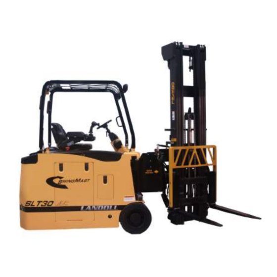
- Page 1 Model SLT30/35 AC Maintenance Manual LANDOLL CORPORATION 1900 North Street Marysville, Kansas 66508 (785) 562-5381 800-428-5655 ~ WWW.LANDOLL.COM F-459-R1 https://www.forkliftpdfmanuals.com/...
- Page 2 https://www.forkliftpdfmanuals.com/...
-
Page 3: Table Of Contents
Intro, Safety, Inspection and Dash Operations Introduction ............. . 1-1 Operating Instructions . - Page 4 Load Wheel Bearing Maintenance ..........2-3 Replacing the Load Tires .
- Page 5 Change the Hydraulic Oil Filter ........... 3-2 Checking and Adjusting Hydraulic Pressure .
- Page 6 Side Shift Circuit Maintenance ........... 4-7 Check Side Shift Circuit Performance .
-
Page 7: Intro, Safety, Inspection And Dash Operations
Replacement Parts When ordering parts that will be used for the repair and maintenance of your Landoll SLT30/35 AC truck, the Figure 1-1: Serial Number and Capacity Plate model and serial number of the truck being repaired will be required. -
Page 8: General Maintenance Instructions
INTRO, SAFETY, INSPECTION AND DASH OPERATIONS Below are the Notice, Caution, Warning and Danger IMPORTANT safety notices and their descriptions that will be used in this book. Maintenance and inspection shall be performed in conformance with the following practices: NOTICE 1. -
Page 9: For Your Safety
INTRO, SAFETY, INSPECTION AND DASH OPERATIONS Battery Safety Rules: 11. All hydraulic systems shall be regularly inspected and maintained in conformance with good practice. Cylinders, valves and other similar parts shall be CAUTION checked to assure that “drift” has not developed to an the extent that it would create a hazard. -
Page 10: Battery Care And Charging
• NEVER smoke or have an open flame near the • Keep battery cover open while charging. battery. Gas formed during charging is • If in doubt, call your local Landoll service technician. explosive and can cause injury. Consult the charger manufacturer’s manual covering your charger for operation and maintenance. -
Page 11: Towing The Truck
INTRO, SAFETY, INSPECTION AND DASH OPERATIONS Towing the Truck General Safety Tips: WARNING • Have the service brake applied when hooking up the tow chain. • Release the emergency brake only when ready to tow the truck and the operator is on the truck being towed. -
Page 12: Cleaning The Truck
• Keep the height of the lifted truck to a minimum. Cleaning the truck Landoll Corporation recommends that their fork trucks NOT be cleaned with a power washer. Electrical boards, circuitry and wiring can be damaged by high pressure water and soap. -
Page 13: Operator's Daily Checklist
INTRO, SAFETY, INSPECTION AND DASH OPERATIONS Operator’s Daily Checklist Date: Inspector: Truck No. Model No. Location Serial No. Shift Hr Meter Hydraulic Oil https://www.forkliftpdfmanuals.com/... - Page 14 INTRO, SAFETY, INSPECTION AND DASH OPERATIONS These checks must be done after 50-100 hours of use. Date: Inspector: Truck No. Model No. Location Serial No. Shift Hr Meter Hydraulic Oil To be performed after 250 hrs of truck operation in addition to the required pre-shift daily inspection.
- Page 15 INTRO, SAFETY, INSPECTION AND DASH OPERATIONS Technicians 250 Hour Checklist Action Needed Landoll / Drexel Status Lift SAFETY & OPERATIONAL CHECKS Description Comments OK - Yes, No Have a qualified technician correct all problems. Mast, Carriage or Attachment Clean, inspect for wear and lube.
- Page 16 Battery Fluid Hydraulic Oil To be performed each 500 hrs of truck operation in addition to the required pre-shift daily inspection Technicians 500 Hour Inspection Action Needed Landoll / Drexel Status Lift SAFETY & OPERATIONAL CHECKS Description OK - Yes, No...
- Page 17 INTRO, SAFETY, INSPECTION AND DASH OPERATIONS To be performed each 1000 hrs of truck operation in addition to the required pre-shift daily inspection. Technicians 1000 Hour Action Needed Landoll /Drexel Inspection Status Lift SAFETY & OPERATIONAL CHECKS Description OK (X)
-
Page 18: Lubrication Specifications
Brush on slide pads *Failure to refill with oil that meets ISO 4406 cleanliness code 15/31/11 may void the warranty. Typical “NEW” oil DOES NOT meet this specification. Contact Landoll Corporation or your lubricant supplier for recommendation. Torque Specifications Component... - Page 19 INTRO, SAFETY, INSPECTION AND DASH OPERATIONS General Torque Specifications (rev. 4/97) This chart provides tightening torques for general purpose applications when special torques are not specified on process or drawing. Assembly torques apply to plated nuts and capscrews assembled without supplemental lubrication (as received condition). They do not apply if special graphite moly-disulfide or other extreme pressure lubricants are used.
- Page 20 INTRO, SAFETY, INSPECTION AND DASH OPERATIONS 37 degree JIC, ORS, &ORB (REV. 10/97 This chart provides tightening torques for general purpose applications when special torques are not specified on process or drawing. Assembly torques apply to plated nuts and capscrews assembled without supplemental lubrication (as received condition). They do not apply if special graphite moly-disulfide or other extreme pressure lubricants are used.
-
Page 21: Tires, Brakes And Drivetrain
Chapter 2 Tires, Brakes and Drivetrain Floor Plate Tire Inspection NOTE WARNING This panel provides access to the accelerator assembly The truck is equipped with tires of a size and which is mounted to the underside of the floor plate. The hardness that provide the necessary traction and master cylinder, service brake pedal and linkage are still maintain a proper shape to minimize tipping. -
Page 22: Visual Inspection
2. Check that the tires remain centered on the wheels. • Undercutting is caused by continuous overloads, rapid, sharp turns, operating on slopes, 3. Use a replacement tire that meets Landoll’s Drexel transporting loads with a high center of gravity, SLT30/35 AC new tire specifications. -
Page 23: Replacing The Drive Tire
NOTE 1. Park the truck at a level, designated work area. Spindle nut can best be removed using Landoll p/n 2. Lower the forks and chock the load wheels. 176168, Tool, M-10SPANNER NUT. -
Page 24: Replacing The Load Tires
• Parts that are not in perfect working condition press hub cap into the hub. should not be used. It is recommended to use only genuine Landoll parts. • Whenever servicing a brake component, it is recommended to service both sides of the truck... -
Page 25: Brake System Service
1. Remove the ignition key and place in a secure area NOTE 2. Perform a Lock Out/Tag Out procedure. Landoll SLT30/35 AC truck braking is accomplished by 3. Jack up and block the truck so the load wheel being using the drive motor to restrain the truck, or by applying serviced is just clear of the floor and free to rotate. - Page 26 TIRES, BRAKES AND DRIVETRAIN 9. Repeat preceding, “Steps 8 through 10” to adjust the NOTE other brake shoe. When you are finished, rotate the wheel a few times to get a feel for the amount of effort In extreme cases of wear, the brake shoes must be fully needed.
-
Page 27: Repairing Brake Wheel Cylinders
TIRES, BRAKES AND DRIVETRAIN 5. Loosen one clamp hold-down screw and remove the 2. Initiate a Lock Out/Tag Out procedure. other screw to allow the clamp to drop down making 3. Raise the side of the truck being serviced. it easier to remove the front and rear return springs. 4. -
Page 28: Hydraulic Brake Drums
TIRES, BRAKES AND DRIVETRAIN Hydraulic Brake Drums 5. If needed, using the rubber mallet (dead-blow hammer), hit the drum on the opposite side, driving it towards the loosened nut. NOTE 6. Repeatedly hit the drum evenly in a circular motion Whenever servicing and/or replacing a brake drum until it pops free, then remove the nut. -
Page 29: Park Brake Installation And Mounting
DO NOT release or operate the truck if you are in doubt about the effectiveness of the parking Figure 2-7: Park Brake Adjustments brake system. Contact your Landoll service representative for assistance. Park Brake Installation and Mounting 1. Remove the dust cover (if applicable). -
Page 30: Brake Pedal Assembly
TIRES, BRAKES AND DRIVETRAIN Figure 2-8: Brake Pedal and Pot Assembly Brake Pedal Assembly Some other areas that can affect the braking system include: • Low fluid level in the master cylinder reservoir. NOTE • Air or leaks in the system. The two piece floor plate is removed to provide access to •... -
Page 31: Bench Bleed The Master Cylinder
TIRES, BRAKES AND DRIVETRAIN Bench Bleed the Master Cylinder 3. Apply the parking brake, disconnect the battery and block the wheels. 1. Support the cylinder in a vise. See Figure 2-9. 4. Remove the floor plates. 2. Remove filler cap assembly. 5. -
Page 32: Bleeding Brakes
TIRES, BRAKES AND DRIVETRAIN Bleeding Brakes IMPORTANT Be careful when handling bleeder screws. Rust may NOTE cause the fitting to break. Spray the fitting with Bleeding the brake system is necessary to remove any penetrating oil before attempting to loosen. Use a air that is trapped when replacing brake lines, brake 6-sided wrench or socket instead of a 12-sided. -
Page 33: Service Brake Pedal Assembly
TIRES, BRAKES AND DRIVETRAIN Service Brake Pedal Assembly Checking Drive Wheel Gearbox 1. With the rear tire raised and supported, spin the drive NOTE wheel and check for noise, rolling resistance and free play. The service brake assembly (brake pedal) includes the mechanical brake pedal assembly, containing a pivot 2. -
Page 34: Gearbox Replacement
TIRES, BRAKES AND DRIVETRAIN 4. To drain, carefully clean the area around the oil filler and oil drain plug. See Figure 2-11. 5. Place a drain pan capable of storing up to 32 ounces (1.0 liter) of fluid under the drain plug. 6. -
Page 35: Traction Drive Motor Service
5. Install floor plate assembly back on the forklift. 6. Install left hand floor plate. 7. Refer to Landoll Setup Procedure, located in “Calibration of Steering and Throttle Pot” starting on page 5-9 to re-calibrate the accelerator module. Replacing Accelerator Module 1. - Page 36 TIRES, BRAKES AND DRIVETRAIN Table provided for general use. NOTES: 2-16 F-459-R1 https://www.forkliftpdfmanuals.com/...
-
Page 37: Hydraulic Oil, Motors, Pumps And Cylinders
• Do not overfill. Having the level above the FULL line does not allow enough area for expansion when the oil heats during normal operation. Cylinders and Valves: Check these components for drift and leakage. Refer to Landoll Corporation and other vendor service information for specifications. F-459-R1 https://www.forkliftpdfmanuals.com/... -
Page 38: Changing Hydraulic Oil
HYDRAULIC OIL, MOTORS, PUMPS AND CYLINDERS 1. Lower the mast to the floor, then tilt it back completely. 2. Turn the key switch to OFF, remove the hydraulic tank access cover. 3. Remove the dipstick, holding the dipstick tip level, check the oil level. -
Page 39: Checking And Adjusting Hydraulic Pressure
10. Tighten the relief valve lock nut. NOTE 11. Set the key to OFF, remove the key from the key For ease of checking hydraulic pressure, Landoll offers a switch and disconnect the battery. Pressure Check Kit (P.N. 0018152) which includes a 12. -
Page 40: Hydraulic Pump Service
6. To relieve any static pressure, SLOWLY loosen and hydraulic spool, Landoll recommends a complete disconnect the pressure and suction hoses from the hydraulic valve replacement. -
Page 41: Mast Service Precautions
• A pressure gauge port is provided, with a WARNING “quick-coupler” (pressure service kit, Landoll p.n. 0018152), for reading the pump pressure on the • Steel toed shoes and eye protection are hydraulic control valve. The pressure check port on... -
Page 42: Hydraulic Fittings And Hoses
HYDRAULIC OIL, MOTORS, PUMPS AND CYLINDERS Hydraulic Fittings and Hoses Check Hydraulic Functions 1. Position the truck on a level, flat surface. Clear area 1. Set the key switch to OFF and remove the key from around the truck. the key switch. 2. - Page 43 HYDRAULIC OIL, MOTORS, PUMPS AND CYLINDERS Figure 3-6: Drive and Steering Motor https://www.forkliftpdfmanuals.com/...
- Page 44 HYDRAULIC OIL, MOTORS, PUMPS AND CYLINDERS Table for your general use with this manual NOTES: F-459-R1 https://www.forkliftpdfmanuals.com/...
-
Page 45: Electrical System
Chapter 4 Electrical System Steering Column/Dash Assembly Key Switch 1. Set the key switch to OFF and remove the key from Removing the Display Panel the key switch. 2. Perform a Lock Out/Tag Out procedure and 1. Set the key switch to OFF and remove the key from disconnect the battery. -
Page 46: Steering Wheel Removal
ELECTRICAL SYSTEM Steering Wheel Removal 1. Remove the lower dash cover. 2. Pry (up) the bellows (rubber boot) free from the 1. Pry the plastic cover from the steering wheel using bellows retainer plate. This exposes the mounting your finger tips. See Figure 4-3. If you cannot grab plate for the steering column and the TFD (Torque the cover, you can start it by carefully using a Feedback Device). -
Page 47: Steering Torque Feedback Device
ELECTRICAL SYSTEM Steering Torque Feedback Device IMPORTANT 1. Remove the lower dash cover weldment. Keep all areas of the battery and the battery cables 2. Tag each electrical connections and disconnect from clean. Dirt or corrosion in these areas can drain the the torque feedback device. -
Page 48: Battery Care
ELECTRICAL SYSTEM • Always assume the battery is emitting hydrogen • Make certain that the battery used meets weight and gases and follow proper safety precautions. size requirements of the truck. NEVER operate the truck with an undersized battery. Reference data •... -
Page 49: Battery Removal
Landoll approved fasteners and be in the correct 3. Perform a Lock Out/Tag Out procedure and assembled order. See Figure 4-5. Refer to the disconnect the battery. -
Page 50: Horn Service
ELECTRICAL SYSTEM Horn Service 8. Tighten cables connected to the high current terminals, identified on the controller housing as B+, B-, U, V and W to 85 +/- 1- in-lbs(10.2 +/- 1.1 Nm). NOTE See Figure 4-5. The horn is located between the frame and the mast. NOTE Removing the horn After replacing the controller it must be reprogrammed. -
Page 51: Truck Lighting
ELECTRICAL SYSTEM Overhead Guard, Lighting and Alarms Replacing the Seat Switch 1. Set the key switch to OFF, remove the key from the Trucks equipped with optional LED flood / headlights, tail key switch and place in a secure area. and stop lights, flashing or spot lights (strobe lights), etc. -
Page 52: Check Side Shift Circuit Performance
ELECTRICAL SYSTEM ESD Strap DANGER Shown below, Figure 4-10, is the ESD Strap which will Hydraulic oil can be under very high pressure. A be installed just in board of the front wheels. This straps pinhole leak is not easily seen and if it pierces will drain all static electricity build up that may occur on your skin, can cause injury and possible death. -
Page 53: Drexel Slt30/35 Ac Calibration Programming
Chapter 5 Drexel SLT30/35 AC Calibration Programming Dashboard Truck Calibration The Drexel SLT30/35 AC truck has many feedback devices and parameters that are accessible and Below is shown the main dash display for reference. programmable using the dash display. Figure 5-1: Headlights and Menu Buttons #1- Headlight Key-Press this button to turn the When prompted, enter the truck password (currently headlights on (if equipped). - Page 54 DREXEL SLT30/35 AC CALIBRATION PROGRAMMING Figure 5-2: Password Screen Once you have correctly entered the truck password, you will enter the dash display menu. This is where you can access and program the truck’s many feedback devices and parameters. Below is shown the main dash display menu screen for reference.
- Page 55 DREXEL SLT30/35 AC CALIBRATION PROGRAMMING #1 “Up Key”- Used to move “UP” through the possible menu selections. #2 ”Down Key” Used to move “DOWN” through the possible menu selections. When this icon appears next to the button, pressing the #3 “Number Key” Used to enter and change the value of button will allow you to exit the submenu and return to the a parameter.
- Page 56 DREXEL SLT30/35 AC CALIBRATION PROGRAMMING Below are “No Run” diagnostics. Parameter Units Throttle Voltage unit 1000 Brake Pot Voltage unit 1000 TFD Current E-Brake Current Pump Contactor Current Main Contactor Current Seat Switch On/Off Battery Rollout Switch On/Off JS Forward Switch On/Off JS Reverse Switch On/Off...
- Page 57 DREXEL SLT30/35 AC CALIBRATION PROGRAMMING Master Setup Parameter Units Default Description Operating Mode 0,1,2 Selects 1 of 3 user customizable operating modes Steer Nominal Resistance % 1000 Sets the minimum resistive feel for the steering wheel Steer Max Resistance 1000 Setrs the maximum resistive feel for the steering wheel...
- Page 58 DREXEL SLT30/35 AC CALIBRATION PROGRAMMING Traction Setup Parameter Units Default Description Throttle High 1000 Sets the throttle high value when calibrating the throttle pot Throttle Low 1000 Sets the throttle low value when calibrating the throttle pot Brake Pot High 1000 Sets the brake pot high value when calibrating...
- Page 59 DREXEL SLT30/35 AC CALIBRATION PROGRAMMING Pump Setup Parameter Units Default Description M1 Max Lift Speed Sets the maximum lift speed percentage for mode 1 M1 Max tilt Speed Sets the maximum tilt speed percentage for mode 1 M1 Max Side Shift Speed Sets the maximum side shift speed percentage for mode 1...
-
Page 60: Clock Set
DREXEL SLT30/35 AC CALIBRATION PROGRAMMING Clock Set 7. Press the button with the icon shown below next to it to exit the “No Run Diagnostic” submenu and return the main menu. Parameter Description Year Sets the year in YY format Month Sets the month in MM format Date... -
Page 61: Wire Guidance Calibration
DREXEL SLT30/35 AC CALIBRATION PROGRAMMING 14. Press the button with the icon shown below next to it to exit back to the main dash display screen. Wire Guidance Calibration 1. Make sure the main dash display screen says “WIRE OFF”. 2. - Page 62 DREXEL SLT30/35 AC CALIBRATION PROGRAMMING During truck calibration and /or truck operation, warnings Attention needs to be given to these warnings to may appear on the Dash Display. prevent damage to the truck. The warnings shown below will “NOT” disable truck operation.
- Page 63 DREXEL SLT30/35 AC CALIBRATION PROGRAMMING See table below. If the warnings shown below appear, IMPORTANT Truck operation “WILL” be disabled. These warnings(Fault Codes) will “NOT” be logged into the truck Immediate attention needs to be given to these error log. warnings.
- Page 64 DREXEL SLT30/35 AC CALIBRATION PROGRAMMING See table below. If the warnings shown below appear, IMPORTANT truck operation “WILL” be disabled. These warnings (Fault Codes) “WILL” be logged into the truck error log. Immediate attention needs to be given to these warnings.
- Page 65 DREXEL SLT30/35 AC CALIBRATION PROGRAMMING Display Possible Possible Message Explanation Solutions Hi Current Pump External short of phase U, V Insure that motor cables are not or W motor connections. shorted. --------------------------------------- --------------------------------------------------- Faulty pump controller. Replace pump controller. Lo Voltage Pump Battery voltage is too low.
- Page 66 DREXEL SLT30/35 AC CALIBRATION PROGRAMMING Display Possible Possible Message Explanation Solutions Steer Lo Voltage Battery voltage is too low. Charge battery. --------------------------------------- --------------------------------------------------- Traction contactor precharge Replace traction contactor precharge circuit is faulty or missing. circuit. --------------------------------------- --------------------------------------------------- Faulty traction contactor. Replace traction contactor.
- Page 67 DREXEL SLT30/35 AC CALIBRATION PROGRAMMING Display Possible Possible Message Explanation Solutions Steer Wheel Fault Steer wheel encoder is not Check to see if steer motor encoder is connected to truck harness. connected to the truck harness. --------------------------------------- --------------------------------------------------- Faulty steer motor encoder. Replace steer motor.
- Page 68 DREXEL SLT30/35 AC CALIBRATION PROGRAMMING Table provided for general use. NOTES: 5-16 F-459-R1 https://www.forkliftpdfmanuals.com/...
- Page 69 DREXEL SLT30/35 AC CALIBRATION PROGRAMMING 5-17 https://www.forkliftpdfmanuals.com/...
- Page 70 DREXEL SLT30/35 AC CALIBRATION PROGRAMMING 5-18 F-459-R1 https://www.forkliftpdfmanuals.com/...
-
Page 71: Truck Lubrication And Chain Maintenance
Chapter 6 Truck Lubrication and Chain Maintenance Figure 6-1: Grease Locations F-459-R1 https://www.forkliftpdfmanuals.com/... -
Page 72: Lubricating The Truck
TRUCK LUBRICATION AND CHAIN MAINTENANCE Lubricating the Truck 1. Before lubricating the truck, lower the forks, set the key switch to the OFF position. 2. Certain grease fittings may include protective plastic caps. Remove them before applying grease. Remember to replace the caps when finished. 3. - Page 73 TRUCK LUBRICATION AND CHAIN MAINTENANCE Figure 6-4: Pivot Pin Clevis Lubricating Figure 6-3: Steering Gears Tilt Cylinder Clevis 1. Turn the truck off and remove the key and place in a secure area. 2. Perform a Lock Out/Tag Out procedure. 3.
-
Page 74: Fork Positioner Lubrication, Non-Side Shifting (Option)
TRUCK LUBRICATION AND CHAIN MAINTENANCE Figure 6-7 Lubricating Tilt Cylinder Clevis Shift Bearing Pads 1. Start the truck and pivot the mast 90 degrees to the right. 2. Shift fully to the right. 3. Turn the truck off and remove the key and place in a secure area. -
Page 75: Chain Lubrication
TRUCK LUBRICATION AND CHAIN MAINTENANCE Measuring Chain Stretch If the chains stretch beyond the recommended amount, they should be replaced in pairs. Chain stretch can be measured with a chain wear scale. See Figure 6-10. The scale indicates whether the distance between two chain links is within tolerance. -
Page 76: Checking And Adjusting Degree Of Tilt
TRUCK LUBRICATION AND CHAIN MAINTENANCE 2. Check to see that an unloaded mast will completely CAUTION lift to full lift height (the relief valve opens). If it will not, check the hydraulic oil level in the reservoir and NEVER exceed 4.0° rear tilt for masts. Rear tilt in add oil if necessary. -
Page 77: Removing The Tilt Cylinders
WARNING Figure 6-12 Adjusting Tilt Cylinder. • Only trained and experienced technicians or your Landoll service representative must be allowed to service the mast assembly. Never Removing the Tilt Cylinders place any part of one’s body into the working area of the mast. - Page 78 IMPORTANT WARNING • DO NOT ATTEMPT THIS REPAIR YOURSELF! Contact your authorized Landoll service representative. The shimming and mast adjustment procedure involves working in the pinch points of the truck and should not be performed by anybody unfamiliar with this procedure.
- Page 79 TRUCK LUBRICATION AND CHAIN MAINTENANCE Figure 6-17 Marking the Frame 8. When finished, apply removable thread locker to the adjustment nuts of both the front and the rear cylinder chain adjusters and to the cylinder clevis lock bolts. See Figures 6-18 and 6-19. Figure 6-15 Setup for Straightedge/Frame Gap Figure 6-16 Adjusting Mast Travel to the Left 6.
- Page 80 TRUCK LUBRICATION AND CHAIN MAINTENANCE Table for your general use with this manual. NOTES: 6-10 F-459-R1 https://www.forkliftpdfmanuals.com/...
- Page 81 Document Control Revision Log: Date Revision Improvement(s) Description and Comments 05/26/15 F-459-R1 Initial Release 10/31/16 F-459-R1 Hydraulic fluid changes - Joshua https://www.forkliftpdfmanuals.com/...
- Page 82 Equipment from Landoll Corporation is built to exacting standards ensured by ISO 9001:2008 registration at all Landoll manufacturing facilities. Model SLT30 AC Maintenance Manual Re-Order Part Number F-459-R1 LANDOLL CORPORATION 1900 North Street Marysville, Kansas 66508 (785) 562-5381 800-428-5655 ~ WWW.LANDOLL.COM Copyright 2016.
Need help?
Do you have a question about the DREXEL SLT30 AC and is the answer not in the manual?
Questions and answers