Table of Contents
Advertisement
Quick Links
Advertisement
Table of Contents

Related Manuals for Baoli EP16-N01

Summary of Contents for Baoli EP16-N01
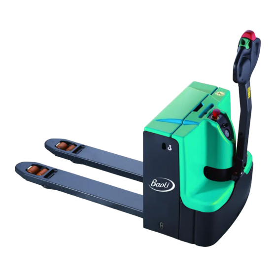
- Page 1 Service & Maintenance Manual Pallet truck EP16-N01 EP20-N04 Warning You must read the instructions in this manual before using the manual. Notice: The last page, please check the file and all of the current product type on the nameplate.
-
Page 2: Table Of Contents
CONTENT FOREWORD…………..………………………………………………………………………..3 1 GENERAL ............................... 4 1.1 INTRODUCTION–MAINTENANCE SAFETY PRECAUTIO ............4 1.2 MEASUREMENT CONVERSIONS ....................7 2 SPECIFICATION ................Errore. Il segnalibro non è definito. 2.1 OVERVIEW OF MAIN COMPONENTS ........Errore. Il segnalibro non è definito. 2.2 TECHNICAL PARAMETER TABLE ..................14 2.3 LUBRICATION ........................... -
Page 3: Foreword
FOREWORD The handling car operation, please read the manual carefully and fully understand the use of the car, improper operation easily lead to danger. This manual describes the different types of pallet truck usage, maintenance truck, please make sure the model is consistent with your company. -
Page 4: General
1. GENERAL 1.1 INTRODUCTION – MAINTENANCE SAFETY PRECAUTIO Maintenance work may cause injuries. Always take care to perform work safe, at least observing the following. It is of utmost importance that maintenance personnel pay strict attention to these warnings and precautions to avoid possible injury to themselves, others or damage to the equipment. A maintenance program must be followed to ensure that the machine is safe to operate. - Page 5 Maintenance vehicles when remove rings, watches and jewelry. Drill grinding or hammer to wear a helmet, safety shoes and work clothes, wear protective glasses. In order to avoid the hurt by prominent parts of the vehicle, the staff must wear safety clothing. Don't wear oily clothes.
- Page 6 work. Park machine company, the ground. In the sulfuric acid toxic battery electrolyte, it can burn skin and clothes of corrosion. If splashed on your clothing or skin sulfate to rinse immediately with plenty of water. For battery to work to wear goggles or safety glasses, if splashed into eyes, ...
-
Page 7: Measurement Conversions
1.2 MEASUREMENT CONVERSIONS Length unit mile 0.01 0.00001 0.3937 0.03281 0.01094 0.000006 0.001 39.37 3.2808 1.0936 0.00062 100000 1000 39370.7 3280.8 1093.6 0.62137 2.54 0.0254 0.000025 0.08333 0.02777 0.000015 30.48 0.3048 0.000304 0.3333 0.000189 91.44 0.9144 0.000914 0.000568 mile 160930 1609.3 1.6093 63360... - Page 8 Pressure unit kgf/cm Pa=N/m lbf/in lbf/ft kgf/cm 0.98067 98066.5 98.0665 14.2233 2048.16 1.01972 100000 14.5037 2088.6 Pa=N/m 0.00001 0.001 0.001 0.00015 0.02086 0.01020 0.01 1000 0.14504 20.886 lbf/in 0.07032 0.0689 6894.76 6.89476 lbf/ft 0.00047 0.00047 47.88028 0.04788 0.00694 kgf/cm =735.56 Torr(mmHg)=0.96784atm STANDARD TIGHTENING TORQUE The following charts give the standard tightening torques of bolts and nuts.
- Page 9 INCH TABLE 4T, 5T Classification Bolt type Bolt size Torque kgf · m (lbf · ft) Torque kgf · m (lbf · ft) 0.6 ± 0.06 1.7 ± 0.2 5/16 1.2 ± 0.12 3.0 ± 0.3 2.0 ± 0.20 5.6 ± 0.5 7/16 3.2 ±...
- Page 10 O – ring PF THREAD Plug Thread Torque (kgf·m) 1.1 ± 0.1 2.6 ± 0.2 4.6 ± 0.3 8.5 ± 0.4 19 ± 1.0 33 ± 2.0 With rotate the nut torque o-rings O – ring Swivel – nut Connector hose Tube O.D (inch) Thread (in)
- Page 11 APPROXIMATE CONVERSIONS Conv Non–SI Conv Unit Factor Unit Factor Unit Torque × 8.9 × 0.113 Newton meter (N·m) = ln·in = N·m × 0.74 × 1.36 Newton meter (N·m) = lb·ft. = N·m × 0.102 × 7.22 Newton meter (N·m) = kg·m = lb·ft.* Pressure (Pa = N/m...
-
Page 12: Specification
2. SPECIFICATION 2.1 OVERVIEW OF MAIN COMPONENTS Electrical box cover Driving wheel Discharge indicator, LED charging Steering wheel parts indicator handle shank hydraulic oil cylinder Drive control switch (switch) butterfly Safety switch button/belly Instrument panel cover Joint emergency button Key switch Pallet fork chassis Load wheel... - Page 13 CONTROL HANDLE Safety switch Lifting switch Drive control switch horn button...
-
Page 14: Technical Parameter Table
2.2 TECHNICAL PARAMETER TABLE Depending on the type of industrial vehicles VDI 2198 standard table EP16-N01 type Fixed the pedal Folding pedals Power (electric, diesel, gasoline, liquefied petroleum electric gas, electrical)gas, electrical) standing steer standing steer Driving mode (manual type, walk, stand driving, car... - Page 15 Drive control Ac speed control According to the EN12053 driver's ear noise level dB(A)
-
Page 16: Lubrication
2.3 LUBRICATION HYDRAULIC OIL The hydraulic oil must have the anti-wear properties, and it is forbidden to different brands or types of oil are mixed together, because their additives or comparable viscosity values may be different. THICKENING OF THE HYDRAULIC OIL Viscosity Features Unit... -
Page 17: Electrical System
3 ELECTRICAL SYSTEM 3.1 ELECTRIC DIAGRAM Electric diagram FUSE01 : 150A FUSE02 : 80 A FUSE1 : 10 A... -
Page 18: Electric Installation
3.2 ELECTRIC INSTALLATION Electrical assembly... - Page 19 ELECTRICAL ASSEMBLY Name Quantity Remarks Dc power supply switch ZDK32-350 Dc power supply switch ZDK32-350 micro switch cross recessed pan head screw M4×25 Micro switch cover Micro switch RZ-15GW2S-B3 hexagon socket cap screws M6x12 Standard spring washer Limit switch mounting plate ZDK32-350 mushroom Dc power supply switch head...
-
Page 20: Driving Wheel
3.3 DRIVING WHEEL FIGURE 14 ROTARY-DRIVEN ASSEMBLY Name Quantity Remarks Electromagnetic brake M8x40 hexagon socket cap screws Standard spring washer Driving wheel seat M8x16 hexagon socket cap screws Small washer A-class handle seat M10x20 hexagon socket cap screws Standard spring washer Elastic cylindrical pin heavy 8x26 Vertical communication drive... -
Page 21: Hydraulic Power Unit
3.4 HYDRAULIC POWER UNIT HYDRAULIC ASSEMBLY Name Quantity Remarks Oil cylinder pin Composite set 20×23×20 Shaft with elastic ring - type A M8x16 hexagon socket cap screws Standard spring washer Dc hydraulic power unit cell Hydraulic hose assembly Seal copper pad Joint bolt... - Page 22 Straight pipe joint hexagon socket cap screws M10x20 Oil cylinder Support ring 50X55X15 Y type sealing ring 50X60X6/7 Dust ring 50X58X5/6.5 piston rod Oil cylinder components Sealing parts...
-
Page 23: Battery Components
3.5 BATTERY COMPONENTS BATTERY COMPONENTS Name Quantity Remarks Charger(Asian Chinese) 24V/25A Charger (Asian English) 24V/25A 24V/25A Charger (European style Charger (Australian) 24V/25A Charger (English-style) 24V/25A Charger (American) 24V/25A Power supply assembly Bolt type welded Power supply assembly Connector components Bolt type battery only Plastic screws Bolt type battery only... -
Page 24: Controller
3.6 CONTROLLER ELECTRICAL CONTROL GROUP Name Quantity Remarks Aluminium sheet controller AC-0-24V/200A Hang line board Traction motor contactor C100/120 DC24V electric relay ACR01F-F-1AD DC24V Bolt the fuse Bolt fuse Copper platoon Bolt fuse 150A Fuse holder for a vehicle BD-1X10A Auto Fuses Main contactor mounts... - Page 25 M8 terminal BD-M8 Copper platoon Programmer plugin fixed frame Flat washer class C Standard spring washer M8x16 hexagon socket cap screws cross recessed pan head M5x10 screw Standard spring washer Flat washer class C cross recessed pan head M4x16 screw Standard spring washer Flat washer class C hexagon socket cap screws...
-
Page 26: Battery Charging And Replacement
Please consider the highest working temperature of the battery REPLACEMENT EP16-N01 Safe parking vehicles, shut off the key switch (8), and press the abrupt stop switch (7) to shut down the vehicle. Open the battery cover and keep upright. Unplug the battery connector (16), and then hanging out the Figure.12: replace the battery... - Page 27 Only when the battery charging right, the right of the LED lights up.As the battery charged condition, leds light up in turn, but only on one at a time. On the left side of the second LED lights flashing, suggests that "energy storage" (70% of the depth of discharge).
- Page 28 MAINTENANCE LIST Table 3 maintenance list Time interval(month)) Hydraulic system Check the hydraulic oil cylinder, piston for damage and leakage Check whether there is damage and leakage of hydraulic fittings and tubing Check the hydraulic oil level if necessary, to fill again ...
- Page 29 Check electromagnetic braking air gap Detection of emergency braking function Detect reverse braking and regenerative braking function Detection of belly switch function Check the steering function Check the function of lifting and lowering Check the handle lever switch function Comprehensive ...
- Page 30 CHECK THE FUSE Remove the main cover, the fuse is located in the position shown in figure 17. Fuse position Figure. 17: Fuse location Table 4: Fuse specification Specification FUSE01 150A FUSE02 FUSE1...
-
Page 31: Electrical Components Replacement
3.8 ELECTRUCAL COMPONENTS REPLACEMENT The bolt with Allen wrench unscrew can remove the cover. REPLACEMENT OF ELECTRIC SCALE, THE KEY SWITCH AND URGENT STOP SWITCH 1. The key switch connector to disconnect 2 The electricity meter connector to disconnect... - Page 32 3 The proximity switch connector to disconnect 4. With four bolts on Allen instrument fixed plate. 5. With cross up remove the two screws on the abrupt stop switch.
- Page 33 6. To remove the mushroom head. 7. With the 2.5 mm wrench to integrate the instrument fixed plate and the leaf shape panel connection of four screws unscrewed. 8. With the 3 mm to dismantle the fixed stop switch and the two screws.
- Page 34 9. Can replace the urgent stop switch. 10. Unscrew the fixed nut, can replace the voltameter. 11. Counterclockwise to dismantle the key switch on the nut, remove the key switch.
- Page 35 REPLACING THE FUSE 1. Using a wrench unscrew the nut corresponding to replacing the fuse Open the fuse seat cover, remove the fuse and replace ELECTRONIC CONTROL OF REPLACEMENT 1. The electric connector pulled up. 2 Using a wrench to electric control + B, B, U, V, W on the bolt...
- Page 36 3.To get off four bolts fixed controller (one on each corner), can change the electric control.
-
Page 37: Tool For Repairing The Pin Of Electric Plug
3.9 TOOL FOR REPAIRING THE PIN OF ELECTRIC PLUG Application Pictures Tool for removal of pins / sleeves Tool for application of pins / sleeves Tool for release of lock Tool for application of secondary locking 2 – pole Tool for application of secondary locking 4 – pole Tool for removal of pins / sleeves... -
Page 38: Hydraulic System
4 HYDRAULIC SYSTEM HYDRAULIC CIRCUIT lift cylinder lowering valve pressure control Throttle valve valve Hydraulic power unit (motor and oil pump) oil box CHECK THE HYDRAULIC OIL Appearance Smell Condition Result Clearly does not change color good good You can use Check viscosity, good... -
Page 39: Cleaning Tank And Filter
4.1 CLEANING TANK AND FILTER Reduce the pallet fork, release the hydraulic oil Remove the pump station Remove the fuel tank Remove the filter Cleaning tank and filter Clean the body fixed plate Use compressed air to clean up, and check whether the filter is invalid or damaged. If the failure or ... -
Page 40: Change Of Pump Station
Filler plug is used ventilation, down by the screw, the air goes out from the tank, it is likely to take out a small amount of hydraulic oil and gas bubble, so there will be oily be soiled screw plug. Watch for a period of time, ensure no leakage phenomenon. -
Page 41: Replace The Hydraulic Oil
3. Remove the connectors by hand 4. With 5 mm twist under two fixed screw, can remove the oil pump. 4.3 REPLACE THE HYDRAULIC OIL... -
Page 42: Replace The Filter
1. Remove the oil pump, unscrewed the cap, then pour out the waste oil, and then tank can be installed into the car, the installation process is the inverse process of disassembly. 2. Through the tubing into the hydraulic oil, twist the lid 4.4 REPLACE THE FILTER... -
Page 43: Replace Carbon Brush
1.In 5 mm Allen wrench unscrew the bolts, remove the oil pump 2. After the oil pump down, can replace filter 4.5 REPLACE CARBON BRUSH 1. With 10 mm open end wrench screw down bolt... - Page 44 2. Open the hood shield 3. With a phillips screwdriver unscrewed the screw, can take out the carbon brush, for replacement.The installation process is the process of inverse process...
-
Page 45: Adjust The Pump Pressure
4.6 ADJUST THE PUMP PRESSURE 1. With 24 mm socket wrench unscrew the bolt 2. Adjust the pressure oil pump with 6 mm, adjust the reoccupy after the completion of 24 mm socket wrench and tighten the bolt... -
Page 46: Driving Wheel
5 DRIVING WHEEL DRIVING WHEEL ASSEMBLY Name Quantity Remarks Electromagnetic brake Hexagon socket cap screws M8x40 Standard spring washer Driving wheel seat Hexagon socket cap screws M8x16 Small washer A-class handle seat Hexagon socket cap screws M10x20 Standard spring washer Elastic cylindrical pin heavy 8x26 Vertical communication drive... -
Page 47: Replace The Drive Wheels
(Note - : when the demolition of driving wheel need 5.1 REPLACE THE DRIVE WHEELS professional lifting equipment, ascends, please pay attention to safety) Unscrew the eight screws, remove the outer cover Pull the plug and socket Using a wrench, unscrew the screw pull wiring, remove the drive wheels... - Page 48 Unscrew five screws, take out the wheels can be replaced...
-
Page 49: Adjust The Brake Of The Air Gap
5.2 ADJUST THE BRAKE OF THE AIR GAP Due to wear and tear, the rated air gap would be a big Z. In order to ensure brake torque, enough in the air gap must be adjusted before peak. Air gap can adjust many times, when the thickness of the friction brake to achieve the minimum value, must change the friction brake disc. -
Page 50: Hand Shank
6 HAND SHANK HANDLE ASSEMBLY Name Quantity Remarks Hexagon socket cap screws M8x25 Canbus control handle C 94300-90 Handle bar assembly Spiale Elastic cylindrical pin - 4X16 straight flute heavy Hexagon socket cap screws M3x20 Interlock switch Hexagon socket cap screws M4x12 Switching floor Gas spring... -
Page 51: Remove The Handle
Envelope Composite cover with 20X22X12 shoulder Handle control wiring harness 6.1 REMOVE THE HANDLE 1.In the punch on the hole, the elastic pin with a hammer to knock out. 2.With the punch will handle shaft to knock out. Note: the handle shaft on the attention to handle drop on hands. -
Page 52: Replace The Gas Spring
6.2 REPLACE THE GAS SPRING 1. Pull out the rubber plug 2. With 6 mm Allen wrench screw down the bolt 3. The fixed gas spring with 13 mm open end wrench unscrew bottom screw... -
Page 53: Change The Interlock Switch
4. Remove the gas spring 6.3 CHANGE THE INTERLOCK SWITCH 1. With 6 mm Allen wrench screw down the bolt 2. Open the handle cover... - Page 54 3. Remove the joint (pay attention to the wiring harness) 4. Remove the switch 5. With a phillips screwdriver unscrewed the screw...
-
Page 55: Replace The Handle Head
6. Can replace the interlock switch 6.4THE HANDLE OF THE HEAD REPLACEMENT 1. Remove the 3 screws can remove the handle back cover. 2. Pull the handle of the connector. 3. Remove the two fixed screw can remove the driver switch. 4. - Page 56 5. Remove the screws on the fixed plate, pull out the connector, then you can replace the circuit board.
-
Page 57: Caster
7 CASTER 7.1 CASTER OPERATION 1 First remove the four bolts be desirable in caster components 2 Unscrew the nut can replace the wheels... - Page 58 3. Remove the bolts 4. Remove the wheels...
- Page 59 5.Remove the shaft with punch, can replace the roller...
-
Page 60: Labels
8. LABELS Label for EU ASSEMBLY (EU) Name Quantity Remarks Prompt labeling Travelling on labeling Load labeling (1600kg) Load labeling (2000kg) Hook labeling CE labeling Refuel labeling... - Page 61 Label for US ASSEMBLY (US) Name Quantity Remarks Prompt labeling Load labeling (5500 LBS) Hook labeling Refuel labeling Warning label Warning label Warning label Warning label Warning label CE labeling folding CE labeling fixed...
-
Page 62: Maintenance List
9 MAINTENANCE LIST Name Quantity Remarks Rubber ring Rubber ring Appearance Rubber ring Rubber ring Composite set 25×28×20 Composite set 20×23×20 Composite set 25×29×25 Composite set 20×22×12 Pressure distribution type oil cup 6 Composite set 25×28×20 Composite set 20×23×20 Composite set 25×29×25 Composite set 20×22×12 Pressure distribution type oil cup 6... - Page 63 Composite set 20×22×12 Deep groove ball bearing 6204 8(双) Load wheel Wheel bearing 84X84 4(双) assembly (EU) Composite cover with 4(双) shoulder18×20×12 Double row angular contact ball bearings Polyurethane spring Steering wheel Composite set 12×15×15 assembly Deep groove ball bearing 6204 Balance wheel 100X40 9 Interlock switch...
-
Page 64: Fault Analysis
10 FAULT ANALYSIS PROGRAMMING UNIT SHOWS CODE FAULT PHENOMENON FAULT DIAGNOSIS BATTERY DISCONNECT FAULT BATTERY NOT CONNECTED 1. BATTERY NOT CONNECTED 2. THE BATTERY CONTACT UNDESIRABLE BRAKE OFF FAULT BRAKE CLOSE FAULT 1.ELECTROMAGNETIC BRAKE COIL SHORT CIRCUIT 2. ELECTROMAGNETIC BRAKE DRIVE OPEN CIRCUIT BRAKE OFF FAULT BRAKE BOOT FAILURE... - Page 65 MAIN OFF FAULT MAIN CONTACTOR COIL 1. THE OPENING OF MAIN DRIVER "OFF"FAULT CONTACTOR COIL ERROR MAIN ON FAULT MAIN CONTACTOR COIL 1. THE CLOSING OF THE MAIN DRIVER “ON”FAULT CONTACTOR COIL ERROR OVERVOLTAGE FAULT THE BATTERY VOLTAGE IS 1.BATTERY VOLTAGE>31V TOO HIGH 2.
- Page 66 THE ACCELERATOR PORT OR ACCELERATOR BREAK DOWN.
Need help?
Do you have a question about the EP16-N01 and is the answer not in the manual?
Questions and answers