
Summary of Contents for Network Equipment Technologies SBC 2000
- Page 1 NET Confidential – Copyright © 2011 Network Equipment Technologies, Inc. All Rights Reserved NET UX SYSTEMS Unified Communications Exchange Customer Documentation (DRAFT) September 2011...
-
Page 2: Table Of Contents
1. Getting To Know The UX ....................2 1.1 UX Status LEDs . -
Page 3: Getting To Know The Ux
Getting To Know The UX This section describes the controls and indicators found on the hardware and in the user interface (UI). UX Status LEDs UX Ethernet and USB Ports UX2000 Rear Panel UX System User Interface UX System Hardware Reference Compliance and Regulatory Information Declaration of Conformity Electromagnetic Compatibility Information... -
Page 4: Ux Ethernet And Usb Ports
1. Power Status LED 2. Alarms Status LED 3. Peer Node Status LED 4. Ready Status LED For more information about the error states of these LEDs, see Status Panel States and Actions 1. Power Status LED This status LED indicates the power conditions of the UX system. The normal state of this LED is on and green. 2. -
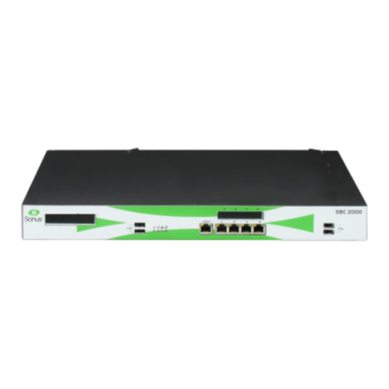
Page 5: Ux2000 Rear Panel
Management Port Your UX comes equipped with a single Management Port which is located adjacent to the bottom set of four Gigabit Ethernet (E1 - E4) ports. UX USB Ports Survivable Branch Appliance (SBA) USB Ports The two SBA USB ports located on the right-hand side of the front panel ..Name Description Reset... -
Page 6: Ux System User Interface
3 Slot 2 Slot 2 for hot-swappable UX Interface Cards 4 Slot 1 Slot 1 for hot-swappable UX Interface Cards 5 Left Power Supply Bay Slot for hot-swappable power supply 6 Right Power Supply Bay Slot for hot-swappable power supply UX System User Interface This section describes the UX System Web-based Graphical User Interface. -
Page 7: Compliance And Regulatory Information
Safety Requirements Power Connection Requirements Restricted Access Location Requirements System Grounding Requirements UX1000 Hardware Specifications UX1000 Power Supplies UX2000 Hardware Specifications UX2000 Power Supplies UX2000 Interface Cards Inserting and Removing Interface Cards T1-E1 PSTN Interface Cards Compliance and Regulatory Information This section provides various compliance and regulatory information related to the safety and operation of the UX product. -
Page 8: Electromagnetic Compatibility Information
Electromagnetic Compatibility Information Product Emission Class The UX system is a Class A product. In a domestic environment this product may cause radio interference in which case the user may be required to take adequate measures. Emission Class Levels... -
Page 9: Product Disposal
Modifications Modifications or changes made to this device, and not approved by Network Equipment Technologies, may void the authority granted by the FCC, or other such agency, to operate this equipment. Federal Communications Commission Notice This equipment has been tested and found to comply with the limits for a Class A digital device, pursuant to Part 15 of the FCC rules. -
Page 10: Ux1000 Fcc And Industry Canada Compliance Statements
Endelig disponering av dette produktet må skje i henhold til nasjonlae lover og forskrifter. A descartagem final deste produto deverá ser efectuada de acordo com os regulamentos e a legislacão nacional. El desecho final de este producto debe realizarse según todas las leyes y regulaciones nacionales. Slutlig kassering av denna produkt bör skötas i enlighet med landets alla lagar och föreskrifter. - Page 11 The following tables list facility interfaces, manufacturer's network interface port designations, RENs or service order codes, and network jacks, This table lists the network trunk interfaces for digital services. Manufacturer Digital Interface Code Service Order Code Network Jack Port Identifier (FIC) (SOC) T1/E1 PSTN...
-
Page 12: Ux2000 Fcc And Industry Canada Compliance Statements
FCC required hearing-aid compatible analog and digital telephones comply with the FCC Rules, Part 68, Section 68.316 and 68.317 for used with the UX1000 Unified Exchange. Programmed Dialer Features When you program emergency numbers or make test calls to emergency numbers using N.E.T. products with programmed dialer features, stay on the line and briefly explain to the dispatcher the reason for the call before hanging up. - Page 13 FCC Registration and Requirements The following paragraphs describe the requirements and information based on FCC rules. Service If you experience problem with the NET - UX2000 Unified Communications Exchange products, contact NET Technical Support Center at 1-800-800-4638 for information on service or repairs. The telephone company can ask you to disconnect the equipment from the network until the problem is corrected or until you are sure that the equipment is not malfunctioning.
- Page 14 registered in accordance with the ACTA adapted ANSI/TIA-968-B standard. Newly Established Network Area and Exchange Codes The routing software features allowing user access to the network must recognize newly established network area codes and exchange codes as they are placed in service. Failure to upgrade the premises systems or peripheral equipment to recognize the new codes as they are established restricts the customers and the customer’s employees from gaining access to the network and to these codes.
-
Page 15: Hardware Expansion Modules
Ringer Equivalence Number (REN) The Ringer Equivalence Number is an indication of the maximum number of devices allowed to be connected to a telephone interface. The termination on an interface may consist of any combination of devices subject only to the requirement that the sum of the RENs of all the devices does not exceed five. -
Page 16: Digital Signal Processing (Dsp) Modules
Setup SBA Task Microsoft Lync SBA Folder Digital Signal Processing (DSP) Modules This page describes the UX2000-DSP-HIGH Digital Signal Processing (DSP) hardware modules for the UX2000 system. DSP modules are hardware modules installed in the UX chassis that provide the call processing horsepower for the UX system. Each DSP module supports up to 100 simultaneous calls, and up to 6 DSP modules can be installed in a UX2000 chassis. -
Page 17: Electrostatic Discharge (Esd) Precautions
Lithium Battery Warning Instruction There is a risk of explosion if the battery is replaced by a battery of an incorrect type. Dispose of used batteries according to the instructions. Electrostatic Discharge (ESD) Precautions To reduce the risk of equipment damage, the UX system should be kept in an electrostatic discharge (ESD) protected environment. The unit should be properly grounded at all times. -
Page 18: Safety Requirements
Location of the ESD Plug on the UX2000 Chassis Rear Panel Safety Requirements This section details the requirements for safe installation and operation of the UX system. Be sure to review this information before placing the system into operation. Restricted Access - The product is for use in a Restricted Access Location only. -
Page 19: Restricted Access Location Requirements
units installed inside the UX chassis, see UX2000 Power Supplies Power Connections and Wiring Provide AC power of nominal 120V/60Hz or 240V/50Hz for the equipment rack or shelf where the UX system is installed. For each line feed supplied to the rack or shelf, a dedicated primary branch circuit protection is required. - Page 20 Grounding Requirements United States and Canada Grounding Connections Europe Grounding Connections Connecting the UX Chassis to Earth Ground To Ground the UX2000 System To Ground the UX1000 System Grounding Requirements UX Series equipment must be grounded to the building ground network. For ground wire specifics, see the tables below for the United States, Canada and Europe.
-
Page 21: Ux1000 Hardware Specifications
Ground Connections on Left Rear Panel of the UX1000 To Ground the UX2000 System Locate the ground connection bolt at the back left corner of the chassis. For UX2000, attach 14 AWG copper wire and a 1-hole UL approved lug to the grounding bolt. Use Panduit PN14-6R or equivalent. To Ground the UX1000 System Locate the ground connection bolt at the back left corner of the chassis. -
Page 22: Ux1000 Power Supplies
Input Voltage AC: 100-240 VAC Nominal, Auto-switching, 47-63 Hz AC Maximum Input Current 2.5A AC Input Voltage Range (nominal) 100-127VAC and 200-240VAC Output +12V/10A Max Power Consumption 150 watts UX power supplies are tested and certified to meet UL / cUL / IEC 60950-1 safety requirements. For more information about the UX power supply units, see UX1000 Power Supplies Networking Interfaces... -
Page 23: Ux2000 Power Supplies
Maximum supported configuration (1RU) - 44 mm / 1.75 in. 444 mm / 17.5 in. 534 mm / 21 in. 23 lbs / 10.43 kgs Environmental Ranges (Operation and Storage) Environmental Parameter Specification Operating Environmental Conditions Temperature: 5º to 40º Celsius Humidity: 5% to 85% RH non-condensing Altitude: 60 meters below sea level to 1800 meters above sea level Storage Environmental Condition... -
Page 24: Ux2000 Interface Cards
AC Input Voltage Range (nominal) 100-127VAC and 200-240VAC Output 300 W-AC: +5V/20A, +12V/24A, -12V/0.6A, +3.3V/20A, +5VSB/3A Max Power Consumption 300 watts UX power supplies are tested and certified to meet UL / cUL / IEC 60950-1 safety requirements. LED Status Indicator The UX power supplies include a LED status indicator on the back of the unit. - Page 25 Inserting an Interface Card You must power down the UX system before installing or removing Interface Cards. Hot swapping of Interface Cards is not supported in UX 1.2. To Insert an Interface Card Carefully insert the card so that the left and right edges slide into the mounting slots. Grip the outside of the attachment levers and push toward the inside of the card until the card locks into place.
-
Page 26: T1-E1 Pstn Interface Cards
T1-E1 PSTN Interface Cards The T1/E1 PSTN Interface card is a TNV1 compliant digital interface card with integrated Channel Service Unit (CSU) function for direct connection to outside plant wiring. This card has board-mounted protection circuits for electrical isolation and protection against power crossing, lightning surges and hazardous voltages. - Page 27 T1/E1 8-Port Card # Name Description 1 Port 1-4 Displays the UXDOC12:status of ports 1 through 4. Status 2 Ports 1-4 Physical ISDN ports 1 through 4. 3 Port 5-8 Displays the UXDOC12:status of ports 5 through 8. Status 4 Ports 5-8 Physical ISDN ports 5 through 8.
-
Page 28: Installing The Ux2000 Hardware
The T1/E1 ports are connected to the public network using 4-wire shielded 26 AWG or larger twisted pair telecommunication line cords with RJ-48 connectors. T1/E1 RJ-48 Connector T1/E1 Connector Pinouts Pin Number Description Receive Ring Receive Tip no connection Transmit Ring Transmit Tip no connection no connection... - Page 29 Preparing for Installation Complete this topic before starting installation of the UX system. To Prepare for UX Chassis Installation Unpack and inspect the UX unit Inspect the unit for any damage, and contact NET to report any problems. Verify that the Interface Cards you purchased are installed in the chassis and properly seated. Keep all packing material until you have successfully placed your UX unit into service.
- Page 30 The illustration above shows the rear bracket assembly for a rack with a 30-inch depth. For racks with a 24-inch depth, do not use the 9-inch extension arm and attach each support bracket directly to the rear rack posts. To Install UX2000 in a 4-Post Equipment Rack Attach the 2 rack mounting ears securely to the front corners of the UX chassis.
- Page 31 Do not block the air vents on either side of the UX chassis. Both sides of the unit must clear to ensure proper cooling of the unit. Installing the UX Chassis in a 2-Post Equipment Rack The UX2000 chassis can be installed in a standard 19-inch, 2-post equipment racks by attaching the rack mounting ears to the middle attachment points on both sides of the chassis.
- Page 32 Installing Interface Cards UX interface cards are delivered separately from the UX chassis. Install the cards in the UX chassis before powering on the unit. For more information about UX interface cards, see Interface Cards. For more information about installing and removing interface cards, see Inserting and Removing Interface Cards You must power down the UX system before installing or removing Interface Cards.
- Page 33 Installing Ground Wire, Power Cables and Connect Power After you have completed the physical installation of the UX chassis, connect the grounding wire and power cables To Install the Grounding Wire and Power Cables Connect a grounding wire to the grounding bolt on the left side of the rear panel, in accordance with System Grounding Requirements Connect power cords to the power supply and electrical sockets.
-
Page 34: Ux2000 Chassis Installation Requirements
If your equipment rack provides dual power circuits and your unit is equipped with a dual power supply, make sure to plug each power supply into a separate power circuit. DO NOT INSTALL ETHERNET OR TELECOM CABLES. You must complete the Initial Configuration before connecting the UX system to your network. - Page 35 Before installing a UX chassis, verify that your installation site meets the following requirements: Restricted Access Area Chassis Mounting Space Equipment Rack Power Connections United States and Canada Europe Grounding Connections United States and Canada Grounding Connections Europe Grounding Connections Restricted Access Area UX Series equipment must be installed in restricted access areas such as dedicated equipment room, or electrical closet, in accordance with Articles 110-26 and 110-27 of the 1999 United States National Electrical Code ANSI/NFPA 70.
-
Page 36: Installing The Ux1000 Hardware
requirements, see the tables below. United States and Canada Requirements Minimum Wire Size 14 AWG Minimum Voltage Rating 300 V Insulation Conductor Stranded Europe Requirements Minimum Wire Size 1.63 mm Minimum Voltage Rating 300 V Insulation Conductor Stranded For more information on UX power requirements, see Power Connection Requirements Grounding Connections... - Page 37 Before installing a UX1000 chassis, verify that your installation site meets the following requirements: Restricted Access Area Chassis Mounting Space Equipment Rack Power Connections United States and Canada Europe Grounding Connections United States and Canada Grounding Connections Europe Grounding Connections Restricted Access Area UX Series equipment must be installed in restricted access areas such as dedicated equipment room, or electrical closet, in accordance with Articles 110-26 and 110-27 of the 1999 United States National Electrical Code ANSI/NFPA 70.
- Page 38 Requirements Minimum Wire Size 14 AWG Minimum Voltage Rating 300 V Insulation Conductor Stranded Europe Requirements Minimum Wire Size 1.63 mm Minimum Voltage Rating 300 V Insulation Conductor Stranded For more information on UX power requirements, see Power Connection Requirements Grounding Connections UX Series equipment must be grounded to the building ground network.
Need help?
Do you have a question about the SBC 2000 and is the answer not in the manual?
Questions and answers