Table of Contents
Advertisement
Grid-Support Utility Interactive
(UL1741, IEEE1547, UL1741 Supplement SA)
Model:
IMPORTANT SAFETY INSTRUCTIONS / SAVE THESE INSTRUCTIONS
Make sure that this instruction manual is delivered to the end user of this product.
・
Read this manual before installing or operating this product. Keep it in a safe place
・
Toshiba Mitsubishi-Electric Industrial Systems Corporation
SOLAR WARE
Photovoltaic Inverter
Installation Manual
PVU-L0800GR
PVU-L0840GR
PVU-L0880GR
NOTICE
Jun. 2020
© TOSHIBA MITSUBISHI-ELECTRIC
INDUSTRIAL SYSTEMS Corporation, 2019
All Rights Reserved
4GBG1009
Rev. D
Advertisement
Table of Contents

Related Manuals for TMEIC PVU-L0800GR

Summary of Contents for TMEIC PVU-L0800GR
- Page 1 SOLAR WARE Grid-Support Utility Interactive Photovoltaic Inverter Installation Manual (UL1741, IEEE1547, UL1741 Supplement SA) Model: PVU-L0800GR PVU-L0840GR PVU-L0880GR NOTICE IMPORTANT SAFETY INSTRUCTIONS / SAVE THESE INSTRUCTIONS Make sure that this instruction manual is delivered to the end user of this product.
-
Page 2: About This Manual
What is prohibited will be described in or near the symbol in either text or picture form. Indicates mandatory action What is mandatory will be described in or near the symbol in either text or picture form. PVU-L0800GR / PVU-L0840GR / PVU-L0880GR Installation Manual... - Page 3 DC Negative voltage Earth ground Caution, risk of electric shock Warning for dangerous voltage Caution, risk of electric shock Energy storage timed discharge Caution, risk of danger Caution, hot surface Refer to the operating instructions PVU-L0800GR / PVU-L0840GR / PVU-L0880GR Installation Manual...
-
Page 4: Limitation Of Use, Disclaimer And Disposal
This product is intended to be used as a grid-connected inverter for photovoltaic generation. Any other use is prohibited. Make sure to consult with TMEIC in case a change in system specifications occurs (e.g. changes in related equipment or other circumstances that may require adjustments to be made to the entire system). -
Page 5: Safety Precautions
■ Do not install the inverter in places where it can be subjected to vibrations (※1) or shocks (※2) Vibrations or shocks may cause performance degradation and/or equipment failure. Forbidden ※1・※2:Refer to “Inverter installation environment” in section 5.1 for details PVU-L0800GR / PVU-L0840GR / PVU-L0880GR Installation Manual... - Page 6 This inverter may cause interference with household appliances if used in residential areas. Such use must be avoided unless the user takes full responsibility and proper measures to prevent interference with radio and Forbidden television broadcast signals. PVU-L0800GR / PVU-L0840GR / PVU-L0880GR Installation Manual...
-
Page 7: Transportation
Mandatory ■ Do not transport, move or place the inverter in the horizontal position Heavy internal components such as transformers and reactors will be subjected to forces that may damage the inverter Forbidden PVU-L0800GR / PVU-L0840GR / PVU-L0880GR Installation Manual... -
Page 8: Storage Environment
If stored in a place where one of the above elements is present, contact failure in circuit breakers and switches may occur, and may lead to performance Forbidden degradation and/ or equipment failure. ※3:Refer to “Inverter installation environment” in section 5.1 for details PVU-L0800GR / PVU-L0840GR / PVU-L0880GR Installation Manual... -
Page 9: Unpacking Of The Inverter
CAUTION ■ Do not transport, move or place the inverter in the horizontal position Heavy internal components such as transformers and reactors will be subjected to forces that may damage the inverter Forbidden PVU-L0800GR / PVU-L0840GR / PVU-L0880GR Installation Manual... -
Page 10: Installation And Wiring Of The Inverter
■ After completing the installation and wiring work, make sure that all protective covers are put in place There is a risk of electric shock and injury if protective covers are not installed. Mandatory PVU-L0800GR / PVU-L0840GR / PVU-L0880GR Installation Manual... - Page 11 If performed in a place where one of the above elements is present, contact failure in circuit breakers and switches may occur, and may lead to performance Forbidden degradation and/ or equipment failure. ※:Refer to “Inverter installation environment” in section 5.1 for details PVU-L0800GR / PVU-L0840GR / PVU-L0880GR Installation Manual...
-
Page 12: Table Of Contents
13.5. Connection of Communication signals....................37 14. Cleaning of the inside of the inverter and its surroundings ................38 15. Inspection after installation and wiring work ....................38 16. Inverter Specifications ........................... 39 17. Contact ................................42 PVU-L0800GR / PVU-L0840GR / PVU-L0880GR Installation Manual... -
Page 13: Tools, Machinery And Materials Required For Installation And Wiring
② Spanner/wrench (for M8、M10、M12、M16) Approx. 300mm ③ Socket Wrench (for M8、M10、M12、M16) ④ Torque Wrench (for M8, M10, M12、M16) ⑤ Pinch Bar (Fig. 4.3) ⑥ Permanent Maker (Red) Fig. 4.3 Pinch Bar ⑦ Other tools for wiring PVU-L0800GR / PVU-L0840GR / PVU-L0880GR Installation Manual... -
Page 14: Installation Environment
■ Do not install the inverter in altitudes over 4000m. Over 2000m : derating The withstand voltage is reduced at high altitudes and could lead to performance degradation and/or equipment failure. PVU-L0800GR / PVU-L0840GR / PVU-L0880GR Installation Manual... -
Page 15: Inverter Installation Environment
Chlorine Gas (Cl *According to IEC- <0.002 <0.01 (Relative Humidity <50%) 654-4 Hydrogen Fluoride (HF) (1987) Class 1 <0.001 <0.005 Ammonia Gas (NH <1 <5 Nitrogen Oxide (NO <0.05 <0.1 Ozone (O <0.002 <0.005 PVU-L0800GR / PVU-L0840GR / PVU-L0880GR Installation Manual... -
Page 16: Installation Clearance
Refer to NEC/NFPA70 and local regulations for required clearance in front of the inverter. Clearance will change if there are other electrical equipment placed in front of the inverter. Fig. 5.1 Inverter Installation Clearance PVU-L0800GR / PVU-L0840GR / PVU-L0880GR Installation Manual... -
Page 17: Electrical Requirements
110% the maximum dc input voltage (1500V). The transformer should be rated more than the capacity of the Inverters connected at secondary side. Other requirements may apply. Ask your TMEIC representative for further transformer requirements. Transformer... -
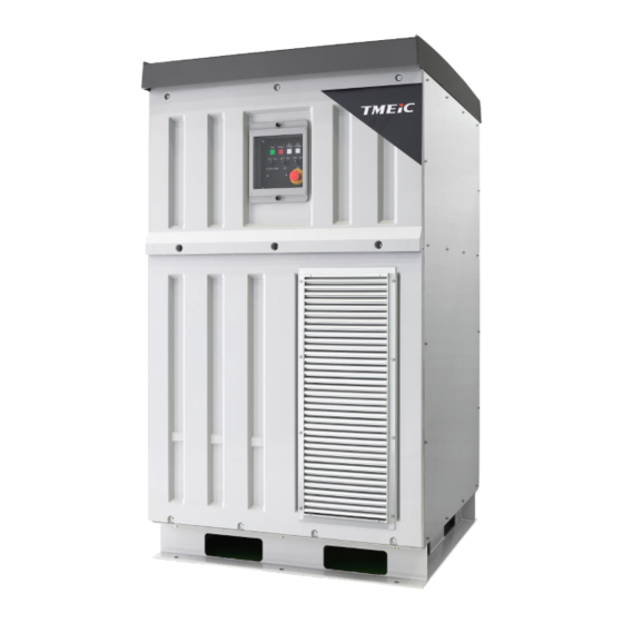
Page 18: Structure And Outline Of The Inverter
4GBG1009 6. Structure and Outline of the Inverter LED Display unit Cooling fans Fork Pockets Front View Rear View Right Side View Left Side View Fig. 6.1 Inverter layout PVU-L0800GR / PVU-L0840GR / PVU-L0880GR Installation Manual... -
Page 19: Inverter Transportation
The package frame provides good protection for the inverter during transportation. However, observe the following precautions (1) Do not apply an impact or shock to the package of over 1.5G. (2) Do not expose the package to salt water or rain. PVU-L0800GR / PVU-L0840GR / PVU-L0880GR Installation Manual... -
Page 20: Storage
Over 1 year Change/supply desiccant according to No.1 or No.2 )indicates the amount of desiccant per 1m 3 of cabinet volume ※4:(g/m ※5:After placing the desiccant inside, seal the cabinet with a shrink wrap PVU-L0800GR / PVU-L0840GR / PVU-L0880GR Installation Manual... -
Page 21: Unpacking
Mechanical shocks and vibrations may cause inverter failure 9.1. Package outline Complete package (Reinforced cardboard) Outer vacuum wrapping Transport protection Fig. 9.1 Inverter package PVU-L0800GR / PVU-L0840GR / PVU-L0880GR Installation Manual... -
Page 22: Main Contents Of The Package
(8) In you notice any abnormality, damage or lack/excess of components, contact us with the packing list number, inverter serial number, quantity and all the necessary information as soon as possible. PVU-L0800GR / PVU-L0840GR / PVU-L0880GR Installation Manual... -
Page 23: Guidelines After Unpacking
Do not touch the internal components of the inverter under any circumstance. (5) Be sure to properly dispose the packaging material after unpacking. PVU-L0800GR / PVU-L0840GR / PVU-L0880GR Installation Manual... -
Page 24: Transportation After Unpacking
Do not attempt to lift the inverter without using the fork pockets when using a fork lift. Center of Center of gravity gravity Insert the forks here Inverter weight: 900kg (1984 lbs) Fig. 9.2 Location of the fork pockets and the center of gravity PVU-L0800GR / PVU-L0840GR / PVU-L0880GR Installation Manual... -
Page 25: Inverter Installation
Refer to the tolerance illustrated Fig. 10.2. (4) Install the inverter onto the skid with proper dimensions and leveled surface. Fig. 10.1 Channel base with its fixation holes Inverter Cabinet Inverter Base Fig. 10.2 Tilt tolerance Tolerance: ±2mm PVU-L0800GR / PVU-L0840GR / PVU-L0880GR Installation Manual... -
Page 26: Fixation Of The Inverter
(3) Tighten the bolts. 11.1. Hardware for inverter fixation Refer to Figure 11.1 Base Frame Lock washer Flat washer (large) Anchor Bolt (M16) Required Torque for M16 bolt (N・m): 108.1 Fig. 11.1 Hardware for inverter fixation PVU-L0800GR / PVU-L0840GR / PVU-L0880GR Installation Manual... -
Page 27: Base Cover Installation
Refer to Figure 12.1 for the installation of base cover. Cover: QTY 4 (same location on the opposite side) Cover: QTY 2 (same location on the opposite side) Front View Right Side View Figure 12.1 Base cover location PVU-L0800GR / PVU-L0840GR / PVU-L0880GR Installation Manual... -
Page 28: Wiring And Connection
Manufacturing Tightened bolt Black Use the colors indicated on the left Soldered point Green column. When the color has poor visibility on the material, a white Commissioning marker can be used. or Repair PVU-L0800GR / PVU-L0840GR / PVU-L0880GR Installation Manual... - Page 29 4GBG1009 Fig. 13.1 Check mark examples PVU-L0800GR / PVU-L0840GR / PVU-L0880GR Installation Manual...
-
Page 30: Connection Of External Cables And Wires
I/O relay signals. Ethernet ports are provided for connection of communication signals. 【Front view】 DC input terminals Equipment grounding conductor terminal 【Rear view】 AC output terminals Grounding electrode conductor terminal I/O terminal Block (#TB1) Communication Port (#CN1) Fig. 13.2 Field wiring terminals location PVU-L0800GR / PVU-L0840GR / PVU-L0880GR Installation Manual... - Page 31 No. of AWG/kcmil AWG/kcmil Conductor Comment Conductor 90C CU 90C AL 1 hole 2 Conductor 1 hole 2 Conductor 1 hole 2 Conductor Note: Select the proper cable following applicable NEC/NFPA70 and local requirements PVU-L0800GR / PVU-L0840GR / PVU-L0880GR Installation Manual...
- Page 32 ※ If there are any small openings between the bottom plate and enclosure, fill them too with putty, etc. If there are openings, dust, moisture, small animals, etc. may enter from there. Example installation 1 Example installation 2 PVU-L0800GR / PVU-L0840GR / PVU-L0880GR Installation Manual...
- Page 33 Note 3: 3 phase output cables between PV inverter and step-up transformer shall be limited up to 20m, they shall be also bundled together. Drain hole SECTION A-A FRONT VIEW Fig. 13.5 BOTTOM VIEW PVU-L0800GR / PVU-L0840GR / PVU-L0880GR Installation Manual...
- Page 34 ※ In particular, note that the items shown in the illustrations below are reported to be damaged sometimes due to contact with cable lugs or other tools during connecting external cables. PANEL Example installation 3 PVU-L0800GR / PVU-L0840GR / PVU-L0880GR Installation Manual...
-
Page 35: Connection Of The Grounding Electrode Conductor And Equipment Grounding Conductors
If you use this terminal for an equipment grounding conductor terminal, it should be used the conductor same as DC side. Rear View Fig. 13.6 Grounding electrode conductor connection (inverter grounding) PVU-L0800GR / PVU-L0840GR / PVU-L0880GR Installation Manual... - Page 36 AWG or kcmil (mm2) Maximum current rating of each input Aluminum or copper-clad Copper aluminum 200 A 6 (13.3) 4 (21.2) 300 A 4 (21.2) 2 (33.6) 400 A 3 (26.7) 1 (42.4) PVU-L0800GR / PVU-L0840GR / PVU-L0880GR Installation Manual...
-
Page 37: Connection Of Input/Output Relay Signals
(OUT) Fig. 13.8 I/O signal relay terminal block ■ After installation and wiring, install all protective covers DANGER There is a risk of electric shock and injury if protective covers are not installed. PVU-L0800GR / PVU-L0840GR / PVU-L0880GR Installation Manual... -
Page 38: Connection Of Communication Signals
Connection of communication cable (To monitoring system) Communication Port (#CN1) Fig. 13.9 Communication port of Ethernet switch After finishing connection of external cable and wires, remove the drain screw shown below. Drain screw PVU-L0800GR / PVU-L0840GR / PVU-L0880GR Installation Manual... -
Page 39: Cleaning Of The Inside Of The Inverter And Its Surroundings
■ After completing the installation and wiring work, make sure DANGER that all protective covers are back in place There is a risk of electric shock and injury if protective covers are not installed. PVU-L0800GR / PVU-L0840GR / PVU-L0880GR Installation Manual... -
Page 40: Inverter Specifications
California Rule 21 Cooling Method Forced air cooling Enclosure Rating Type NEMA 3R 1100mm x 1100mm x 1900mm Inverter Dimensions (H x W x D) (43.3 in x 43.3 in x 74.8 in) PVU-L0800GR / PVU-L0840GR / PVU-L0880GR Installation Manual... - Page 41 California Rule 21 Cooling Method Forced air cooling Enclosure Rating Type NEMA 3R 1100mm x 1100mm x 1900mm Inverter Dimensions (H x W x D) (43.3 in x 43.3 in x 74.8 in) PVU-L0800GR / PVU-L0840GR / PVU-L0880GR Installation Manual...
- Page 42 California Rule 21 Cooling Method Forced air cooling Enclosure Rating Type NEMA 3R 1100mm x 1100mm x 1900mm Inverter Dimensions (H x W x D) (43.3 in x 43.3 in x 74.8 in) PVU-L0800GR / PVU-L0840GR / PVU-L0880GR Installation Manual...
-
Page 43: Contact
Reconnection time setting is at 300s default, but has field adjustable settings from 7s to 600s. 17. Contact For technical inquires, order of spare parts or repairs, please contact your local TMEIC sales or service representative. PVU-L0800GR / PVU-L0840GR / PVU-L0880GR Installation Manual... - Page 44 TOSHIBA MITSUBISHI-ELECTRIC INDUSTRIAL SYSTEMS CORPORATION...
Need help?
Do you have a question about the PVU-L0800GR and is the answer not in the manual?
Questions and answers