Table of Contents
Advertisement
Quick Links
Advertisement
Table of Contents

Summary of Contents for Moog Tritech DMD
- Page 1 Diver Mounted Display (Tethered) Product Manual 0747-SOM-00002 Issue 02...
-
Page 2: Table Of Contents
Table of Contents Help & Support ............................. 3 Warning Symbols ............................4 Introduction ..............................5 General Overview ............................5 Technical Specification ..........................6 Physical Dimensions 1200ik & 720ik ...................... 6 DMD SCU Specifications ........................... 7 Monocle Specifications ..........................8 Subsea Computer (SSC) Specifications ....................9 Tether Specifications .......................... -
Page 3: Help & Support
Westhill, Aberdeenshire AB32 6JL, UK Telephone +44(0)1224 744 111 Email tritech-support@moog.com Website www.moog.com/tritech Prior to contacting Tritech International Ltd please ensure that the following is available: 1. The Serial Numbers of the product and any Tritech International Ltd equipment connected directly or indirectly to it 2. -
Page 4: Warning Symbols
Warning Symbols Throughout this manual the following symbols may be used where applicable to denote any particular hazards or areas which should be given special attention: Note This symbol highlights anything which would be of particular interest to the reader or provides extra information outside of the current topic. Important When this is shown there is potential to cause harm to the device due to static discharge. -
Page 5: Introduction
Introduction General Overview The DMD system has been designed to provide divers with the ability to navigate and carry out inspections in zero visibility conditions. Utilising the Gemini range of Multibeam imaging sonars allows the user to select the most suitable sonar for the type of operation required. -
Page 6: Technical Specification
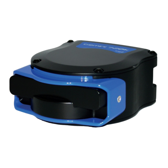
Technical Specification The system is designed to be used with our Gemini range of multibeam sonars – primarily the • 1200ik with inodive mounting plate • 720ik with inodive mounting plate Physical Dimensions 1200ik & 720ik Please refer to the 1200ik & 720ik manuals available on our website www.tritech.co.uk for full sonar specifications... -
Page 7: Dmd Scu Specifications
DMD SCU Specifications Surface Control Unit (SCU) SCU Rugged Case Laptop - Toughbook 55 (only used with DMD-T) Internal rechargeable Power Internal rechargeable power battery >4hrs (for a dual battery Duration of operation Up to 19 hours system) IP rating Weatherproof IP53 Battery chemistry... -
Page 8: Monocle Specifications
Monocle Specifications Monocle specification Power requirement 0.5W @ +5V DC Depth rating 100m Display input RGB, HSYNC, VSYNC Display resolution SVGA (800 X 600) Connector SubConn Micro Circular series Weight in water 0.09kg 0747-SOM-00002-02 Page 8 of 33... -
Page 9: Subsea Computer (Ssc) Specifications
Subsea Computer (SSC) Specifications Subsea computer Power requirement 10W @ 20 - 42 VDC Depth rating 100m Connectors SubConn Micro Circular series Weight in water 0.54kg Does not allow for attached accessories Tether Specifications Tether (only used with DMD-T) Cable length 100m Connectors SubConn Micro Circular series... -
Page 10: Hardware Installation & Configuration
Hardware Installation & Configuration The full DMD system is contained within 4 separate rugged deployment transit cases These are • DMD SCU • DMD Instrument Deployment Case • DMD Diver to Surface – Deployment Case • DMD Sonar Deployment Case DMD Surface Control Unit (SCU) The DMD SCU case is a self-contained rugged transit case featuring integrated connection points on its rear which provide all the surface connections required which power run and deploy the system... - Page 11 DMD SCU Input of the SCU 30V-55V 3.3A Output of SCU 42.5V 2.5A Output of External AC/DC PSU S12445 * 3.13A *subject to change Internal Batteries (x2) Capacity 5500mAh \ Energy 198Wh Charging Instructions The internal batteries will automatically charge with the application of input power.
- Page 12 F1 F2 The shipping fuses should be removed to isolate the batteries for air transportation. Shipping Fuses re-instatement Following the re-instatement of the shipping fuses, the charge status (%) reported to Genesis will be incorrect until the batteries are fully charged or fully discharged. Connection Panel on rear of DMD SCU 0747-SOM-00002-02 Page 12 of 33...
-
Page 13: Dmd Instrument Deployment Case
DMD Instrument Deployment Case The DMD Instrument Deployment case is a rugged transit case featuring bespoke cut-outs for safely storing and transporting all the items and accessories (other than the sonar head) required to install and deploy the system on site. Tier 1 TOP LEVEL The case consists of three removable trays... - Page 14 Tier 2 MIDDLE LEVEL 12445 SCU Power Supply unit Toughbook Transformer 00025 Mains lead for SCU Mains Lead for Toughbook 12420 Topside Diver Audio Cable 12504 Subconn MCDC12F 12505 Subconn MCDC10M 09174 Subconn MCDC6M 12506 Subconn MCDC8M 12507 Subconn MCDC10F 10071 Subconn MCDC8F 11541 Subconn MCDC6F 12523 Accessories Kit Box...
-
Page 15: Dmd Sonar Deployment Case
DMD Sonar Deployment Case The DMD Sonar Deployment case is a rugged transit case featuring bespoke cut-outs for safely storing and transporting the Gemini 720ik or 1200ik multibeam sonar heads. ITEM DESCRIPTION Gemini 720ik or 1200ik Spare Pocket Space Cable Stowage Space 2mm Allen Key CD Case Stowage Space Document Space... -
Page 16: Dmd Diver To Surface - Deployment Case
DMD Diver to Surface - Deployment Case The DMD Diver to Surface Deployment case is a large rugged transit case used to store and transport the main diver to surface umbilical. The umbilical can be coiled within in a ‘figure 8’ configuration which makes deploying straight from the case simpler. -
Page 17: System Connections - Subsea
System Connections – SUBSEA The diagram above shows the cable connections required at the SSC before the system is powered on and deployed Particular care should be taken to ensure that the blanking plug item 4 is fitted if not utilising the diver comms pass-thru option on the SSC. -
Page 18: System Connections - Surface
System Connections – SURFACE The diagram above shows the cable connections required at the DMD Surface Computer before the system can be powered on and deployed PART ITEM NO. QTY DESCRIPTION NUMBER 12341 DMD SURFACE CONTROL UNIT 09992 PX0840-B-2M00 IP68 USB CABLE 12441 PANASONIC TOUGHBOOK FZ-55 12445... -
Page 19: Assembly & Fitting Of Sonar Onto Mask (Using The Ots Accessory Rails)
Assembly & Fitting of Sonar onto Mask (Using the OTS Accessory Rails) The diagram above shows the parts required to construct and mount the sonar onto the OTS Guardian diver mask Item Part No. Description S12055 OTS Guardian Accessory Rail S12051 Spigot Assembly, 90 degree S12049... - Page 20 The illustrations below show the mounting fully assembled and attached to the side of the mask. During use the diver may find it helpful to reach up and adjust the orientation of the sonar slightly using gentle pressure to rotate it forward or backward on the mounting spigot.
-
Page 21: Assembly & Fitting Of Monocle Onto Mask (Using The Ots Accessory Rails)
Assembly & Fitting of Monocle onto Mask (Using the OTS Accessory Rails) The diagram above shows the parts required to assemble and mount the Monocle onto the OTS Guardian diver mask Item Part No. Description S12055 OTS Guardian Accessory Rail S12363 Clamping Slide with 1/4"... - Page 22 • When positioned for comfort and best view for the diver re-tighten the knurled section [4] and 2.5mm hex screw [5] to lock in place. The monocle assembly is designed to allow it to be flipped up and out of the view of the diver if required.
-
Page 23: Monocle Orientation
Monocle Orientation The monocle can be configured in any one of 3 separate configurations: • For fitment and use over the divers LEFT EYE only • For fitment and use over the divers RIGHT EYE only • Neutrally, can be used over EITHER EYE (in this configuration cable routing may not be ideal) LEFT EYE RIGHT EYE... -
Page 24: Dmd System Operation
DMD System Operation Switch ON & Start-Up Sequence When all connections have successfully been made to both the surface & subsea equipment as per the manual sections ‘System Connections – SUBSEA’ & ‘System Connections – SURFACE’ the equipment can then be powered ON. IMPORTANT –... - Page 25 The software is now initiated and waiting for a connection with the SSC • Power On the DMD SCU this will power up the SSC (Subsea Computer), the connected sonar head and DMD monocle DMD SCU POWER BUTTON • Once the SSC has booted up it will establish comms with the DMD SCU •...
-
Page 26: Software Display & Operation
Software Display & Operation On the Tethered DMD system the Genesis sonar display screen will appear slightly differently when viewed on the Divers display monocle or the Surface Operators laptop. This is because all inputs which alter the control and display of the sonar image must be made by the surface control operator, the diver has no direct control and simply views the sonar image. - Page 27 Monocle Brightness The brightness of the monocle can be adjusted to suit the ambient conditions of the dive location. For example if the dive zone is very dark with very little ambient light then it may be advantageous to reduce the monocle brightness to avoid glare affecting the diver’s peripheral vision. The adjustment of monocle brightness is made via the software GUI from the surface control computer.
-
Page 28: Updating The Genesis Software Version On The Ssc
Updating the Genesis software version on the SSC The Tethered system is supplied with a content management cable assembly. When plugged into the sonar port on the SSC this cable enables an Ethernet connection to be setup between the SSC and the users PC or laptop. - Page 29 The illustration below shows the different items needed to connect the SSC to the PC and how they are connected. The SubConn to Souriau adapter cable [2] allows connection between the Content Management Cable [3] and DMD Subsea Computer [1]. The system is powered by the supplied AC to 24V DC power supply [4] and te RJ45 plug on the Content Management Cable [3] into the Ethernet Network Adapter of your PC.
- Page 30 Connect the content management cable to the SSC and launch the software to connect with the SSC. The current version of Genesis software installed on the SSC will be displayed in the status message highlighted by the RED box. Click on File and then on System Update.
- Page 31 The installer will start unzipping and transferring the files to the SSC When this process has concluded the message ‘Script Execution Completed! Please wait…’ will be displayed After a wait of around 15 seconds the message ‘The Subsea Computer Updated successfully!’ will be displayed.
-
Page 32: General System Operation
General System Operation Sonar Operational Notes When using a dual frequency 1200ik multibeam sonar there are some operational factors which must be considered in order to make best use of the dual channel capability of the sonar. Dual Frequency Options 720 kHz Low Frequency Operation The sonar has a 120°... -
Page 33: System Storage Specifications & Recommendations
System Storage Specifications & Recommendations The equipment should, whenever possible, be stored in its original transportation cases until ready for operation. During storage, each box must not be used for any purpose for which it was not intended (work platform, table, steps etc.). After unpacking and during storage all equipment must be kept in a dry, non condensing atmosphere, free from corrosive agents and isolated from sources of vibration.
Need help?
Do you have a question about the Tritech DMD and is the answer not in the manual?
Questions and answers