Table of Contents
Advertisement
Available languages
Available languages
Quick Links
Advertisement
Table of Contents

Subscribe to Our Youtube Channel
Summary of Contents for AS VIVA MG5
- Page 1 BETRIEBSANLEITUNG / MANUAL VERSION: I-BU www.AsVIVA.de...
-
Page 2: Table Of Contents
INHALTSVERZEICHNIS GEWÄHRLEISTUNGSBESTIMMUNGEN ....................3 WICHTIGE HINWEISE ZU IHREM PRODUKT ..................4 WICHTIGE SICHERHEITSHINWEISE ....................5 PRODUKTZEICHNUNG..........................7 EXPLOSIONSZEICHNUNG........................8 TEILELISTE ...............................9 MONTAGETEILE .............................10 SPEZIFIKATIONEN...........................12 MONTAGE ..............................13 AUFWÄRMEN UND DEHNEN ........................24 GEWÄHRLEISTUNGSRECHT ......................26 TABLE OF CONTENTS WARRANTY TERMS ..........................28 IMPORTANT INFORMATION ABOUT YOUR PRODUCT ..............29 IMPORTANT SAFETY INSTRUCTIONS ....................30 OVERVIEW ..............................32 EXPLODED DIAGRAM ...........................33 PARTS LIST .............................34... -
Page 3: Gewährleistungsbestimmungen
Teilen Sie uns bitte anhand der Teileiste die genaue Teilenummer mit. Liegt eine Störung beim Gerät vor? Sollten Sie die Möglichkeit einer Videoaufnahme, z.B. mit einer Handykamera haben, nehmen Sie die Störung auf und senden Sie uns das Video- oder Bildmaterial zu. As-STORES GmbH Kohnacker 9a D-41542 Dormagen Internetadresse:... -
Page 4: Wichtige Hinweise Zu Ihrem Produkt
Sollte dennoch eine Fehlfunktion auftreten, Ihnen das Produkt nicht zusagen oder sollten Sie Anmer- kungen und Vorschläge haben, so bitten wir Sie nicht zu zögern und Kontakt mit unserem Support aufzunehmen, unter support@as-stores.com. Wir werden gemeinsam mit Ihnen eine Lösung finden. WAS IST ZU BEACHTEN? •... -
Page 5: Wichtige Sicherheitshinweise
WICHTIGE SICHERHEITSHINWEISE • Das Sicherheitsniveau des Gerätes kann nur gehalten werden, wenn es regelmäßig auf Schäden und Verschleiß geprüft wird. Dabei ist ein besonderes Augenmerk auf die die beweglichen Elemente zu richten. • Wenn Sie dieses Gerät weitergeben oder von einer anderen Person benutzen lassen, stellen Sie sicher, dass derjenige den Inhalt dieser Gebrauchsanleitung kennt. - Page 6 WICHTIGE SICHERHEITSHINWEISE Bitte lesen Sie die Anleitung genau durch, bevor Sie mit den Zusammenbau beginnen! Achten Sie beim Anziehen der Schraubverbindungen darauf, dass der Bewegungsablauf nicht durch zu festes anziehen beeinträchtigt wird. Bewegliche Gelenkteile ( Gleitträger usw. ) müssen von Zeit zu Zeit mit handelsüblichem Schmierfett eingefettet werden.
-
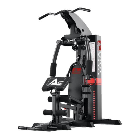
Page 7: Produktzeichnung
PRODUKTZEICHNUNG... -
Page 8: Explosionszeichnung
EXPLOSIONSZEICHNUNG... -
Page 9: Teileliste
TEILELISTE Teil Beschreibung Menge Teile Nr. Beschreibung Menge Rear Base Frame 53-1 Pulley Bracket Front Base Frame 53-2 Pulley Bracket Low Row Base Frame 53-3 Bracket Rear T Base Frame 53-4 Crossed Double Floating Pulley Bracket Foot Plate 53-5 L-shaped Pin Left&Right Base Frame 53-8 Axle (57 mm) -
Page 10: Montageteile
MONTAGETEILE... - Page 11 MONTAGETEILE...
-
Page 12: Spezifikationen
ÜBERSICHT SPEZIFIKATIONEN • Maße: 208 x 140 x 210 cm • Einzelmaß Sitz: 24,5 x 39 x 5 cm • Einzelmaß Rückenlehne: 31 x 60 x 5,5 cm • Einzelmaß Armlehne: 31 x 60 x 5,5 cm • Gewicht: 156 kg •... -
Page 13: Montage
MONTAGE SCHRITT 1 1. Verbinden Sie zunächst den Hauptrahmen (2) und den hinteren T-Rahmen (4) mit dem hinteren Verbindungsrahmen (1). Befestigen Sie diese mit einer Schraube (56-1), einer Unterlegscheibe (56-12) und einer Mutter (56-14). 2. Befestigen Sie den linken und rechten Rahmen (6) an den Hauptrahmen (2). Sichern Sie diese mit einer Schraube (56-1), einer Unterlegschraube (56-12) und einer Mutter (56-14). - Page 14 MONTAGE SCHRITT 2 1. Schieben Sie zunächst die Gummipuffer (54-1) von unten auf die Führungsstangen (7). Setzen Sie die Führungsstangen (7) in die Löcher des hinteren Verbindungsrahmens (1) ein und befestigen Sie diese mit zwei Schrauben (56-3) und zwei Unterlegscheiben (56-12). 2.
- Page 15 MONTAGE SCHRITT 3 1. Befestigen Sie den vertikalen Rahmen (10) am Hauptrahmen (2) und sichern Sie beiden Teile mit zwei Unterlegscheiben (56-12) und zwei Muttern (56-14). 2. Befestigen Sie die Hauptsitzstütze (11) am Hauptrahmen (2) und sichern Sie diese ebenfalls mit zwei Unterlegscheiben (56-12) und zwei Muttern (56-14).
- Page 16 MONTAGE SCHRITT 4 1. Verbinden Sie den oberen Rahmen (13) mit den Führungsstangen (7) und sichern diese mit Schrau- ben (54) und Unterlegscheiben (67). Befestigen Sie nun den oberen Rahmen (13) am vertikalen Rahmen (10) mit Hilfe von Schrauben (56-1), Unterlegscheiben (56-12), Muttern (56-14) und einem Verbinder (53-3).
- Page 17 MONTAGE SCHRITT 5 1. Fädeln Sie alle Kabel (22-1, 22-2 und 22-3) wie in der Abbildung dargestellt durch die jeweiligen Führungen. Hinweis: Machen Sie erst mit Schritt 2 weiter, wenn alle Kabel eingefädelt sind. 2. Montieren Sie die Riemenscheiben (23) wie in der Abbildung dargestellt. 3.
- Page 18 MONTAGE SCHRITT 6 1. Fixieren Sie nun alle Teile mit den entsprechenden Schrauben. Richten Sie sich hierbei nach der Abbildung in Schritt 6.
- Page 19 MONTAGE SCHRITT 7 1. Befestigen Sie die Rückenauflage (19) am vertikalen Rahmen (10) und sichern Sie diese mit zwei Schrauben (56-9) und Unterlegscheiben (56-12). 2. Legen Sie den Sitz (20) auf den Sitzständer (17) und sichern Sie diesen mit Schrauben (56-8) und Unterlegscheiben (56-12).
- Page 20 MONTAGE SCHRITT 8 1. Befestigen Sie die obere Rahmenabdeckung (48) am oberen Rahmen (13) und am vertikalen Rahmen (10). Verwenden Sie hierfür Schrauben (56-7) und Unterlegscheiben (56-12).
- Page 21 MONTAGE SCHRITT 9 1. Führen Sie zwei Schaumstoffrohre (28) zur Hälfte durch die Löcher der Beinentwickler (12) und der Hauptsitzhalterung (11). 2. Schieben Sie die Schaumstoffrollen (29) über beide Enden auf die Schaumstoffrohre (28). Stecken Sie anschließend die Verschlusskappen (54-3) an die Enden der Schaumstoffrollen (29).
- Page 22 MONTAGE SCHRITT 10 1. Bringen Sie die linke Hantelscheibenabdeckung (30) und die rechte Hantelscheibenabdeckung (31) am oberen Rahmen (13), hinteren Verbindungsrahmen (1) und dem Hauptrahmen (2) an. Sichern Sie diese mit Schrauben (56-7) Unterlegscheiben (56-12) und Muttern (56-15).
- Page 23 MONTAGE SCHRITT 11 1. Befestigen Sie nun die zwei Hantelscheibenabdeckungen mit den Schrauben (56-16) und (56-17). HINWEIS: • Bevor Sie das Fitnessgerät benutzen, ziehen Sie alle Schrauben und Muttern erneut fest. • Bevor Sie das Fitnessgerät benutzen, ziehen Sie das Stahlseil und die Riemenscheibe fest an.
-
Page 24: Aufwärmen Und Dehnen
AUFWÄRMEN UND DEHNEN Aufwärmphase und Abkühlphase 1. Aufwärmphase 5 bis 10 Minuten Gymnastik und Stretching. Vorbereitung des Organismus auf die bevorstehende Traingsleistung. 2. Trainingsphase 15 bis 40 Minuten intensives aber nicht zu überfordendes Training 3. Abkühlphase 5 bis 10 Minuten Gymnastik und Stretching um die Muskulatur zu lockern und Muskelkater vorzu- beugen. - Page 25 AUFWÄRMEN UND DEHNEN Dehnung der hinteren Oberschenkmuskulatur: Setzen Sie sich auf den Boden und strecken Sie Ihrrechtes Bein. Winkeln Sie Ihr linkes Bein so an, dass die Fußsohle die Innenseite Ihres rechten Oberschenkels berührt. Beugen Sie sich nun so weit wie möglich nach vorne und versuchen Sie, die Zehen an Ihrem rechten Bein zu berühren.
-
Page 26: Gewährleistungsrecht
GEWÄHRLEISTUNGSRECHT Herzlichen Glückwunsch zu Ihrer Entscheidung zum Kauf eines Produkts aus dem Hause AsVIVA. Gemäß des zum 01. Januar 2002 geänderten europäischen Gewährleistungsrechts, steht Ihnen eine gesetzliche Gewährleistungsfrist von 2 Jahren zu. Die Gewährleistungsfrist beginnt mit der Übergabe der Ware durch den Fachhändler. Zum Nachweis des Kauf- bzw. -
Page 28: Warranty Terms
Please tell us the exact part number using the parts list. 2. Is there a fault with the unit? Should you have the possibility of a video recording e.g. mobile phone camera, pickup the error and send us the video or picture material. As-STORES GmbH Kohnacker 9a D-41542 Dormagen Internetadresse:... -
Page 29: Important Information About Your Product
IMPORTANT INFO ABOUT YOUR PRODUCT Thank you for being our valued customer. We are grateful for the confidence you have placed in us and hope we met your expectations. In order to deliver an impeccable product, all our products are subjec- ted to a comprehensive quality control. -
Page 30: Important Safety Instructions
When you have children trained on the device, you should consider their mental and physical development and, above all, their temperament. You should supervise the children, if necessary, and should point out the correct use of the appliance. As a toy, the training equipment is by no m- ans suitable. - Page 31 If you experience dizziness, nausea, chest pain, or other abnormal symptoms, stop training and consult immediately your doctor. • Persons such as children, disabled persons and disabled persons should only use the appliance in the presence of another person, who can provide help and guidance. •...
-
Page 32: Overview
OVERVIEW... -
Page 33: Exploded Diagram
EXPLODING DRAW... -
Page 34: Parts List
PARTS LIST Description Description Rear Base Frame 53-1 Pulley Bracket Front Base Frame 53-2 Pulley Bracket Low Row Base Frame 53-3 Bracket Rear T Base Frame 53-4 Crossed Double Floating Pulley Bracket Foot Plate 53-5 L-shaped Pin Left&Right Base Frame 53-8 Axle (57 mm) Guide Rod... -
Page 35: Assembly Parts
ASSEMBLY PARTS... - Page 36 ASSEMBLY PARTS...
-
Page 37: Specifications
SPECIFICATION • Maße: 208 x 140 x 210 cm • Einzelmaß Sitz: 24,5 x 39 x 5 cm • Einzelmaß Rückenlehne: 31 x 60 x 5,5 cm • Einzelmaß Armlehne: 31 x 60 x 5,5 cm • Gewicht: 156 kg •... -
Page 38: Assembly
ASSEMBLY STEP 1 1. First connect the main frame (2) and the rear T-frame (4) with the rear connecting frame (1). Fix those pieces with the bolt (56-1), washer (56-12) and the nut (56-14). 2. Attach the left and the right frames (6) to the main frame (2). Fix them with the bolt (56-1), washer (56-12) and a nut (56-14). - Page 39 ASSEMBLY STEP 2 1. First slide the rubber buffers (54-1) from below onto the guide rods (7). Insert the guide rods (7) into the holes of the rear connecting frame (1) and fasten them with two bolts (56-3) and two washers (56-12).
- Page 40 ASSEMBLY STEP 3 1. Attach the vertical frame (1) to the main frame (2) and secure both parts with two washers (56-12) and two nuts (56-14). 2. Attach the main seat support (11) to the main frame (2) and fix it with two washers (56-12) and two nuts (56-14).
- Page 41 ASSEMBLY STEP 4 1. Connect the upper frame (13) to the guide rods (7) and secure them with bolts (54) and washers (64). Then attach the upper frame (13) to the vertical frame (10) using bolts (56-1), washers (56- 12), nuts (56-14) and a connector (53-3). 2.
- Page 42 ASSEMBLY STEP 5 1. Thread all calbles (22-1, 22-2 and 22-3) trough the respective guides as shown in the illustration. NOTE: Do not cintinue with step 2 until all cables are threaded. 2. Mount the pulleys (23) as shown in the illustration.
- Page 43 ASSEMBLY STEP 6 1. Fix all parts with the appropriate bolts. Use the illustration in step 6 as a guide.
- Page 44 ASSEMBLY STEP 7 1. Attach the backrest (19) to the vertical frame and secure it with two bolts (56-9) and washers (56-12). 2. Place the seat (20) on the seat stand (17) and secure it with bolt (56-8) and washer (56-12). 3.
- Page 45 ASSEMBLY STEP 8 1. Attach the top frame cover (48) to the top frame (13) and the vertical frame (10). Secure them with bolts (56-7) and washers (56-12).
- Page 46 ASSEMBLY STEP 9 1. Insert two foam tubes (28) halfway trough the holes of the leg developers (12) and the main seat support (11). 2. Slide the foam rolls (29) over both ends onto the foam tubes (28). Then push the closing caps (54-3) onto the ends of the foam rolls.
- Page 47 ASSEMBLY STEP 10 1. Attach the left weight plate cover (30) and the right weight plate cover (31) to the upper frame (13), rear connecting frame (1) and the main frame (2). Secure it with bold (56-7), washer (56-12) and nuts (56-15).
- Page 48 ASSEMBLY STEP 11 1. Fasten the two weight plate covers with the bolts (56-16) and (56-17). NOTE: • Before using the fitness equipment, please tighten all bolts and nuts. • Before using the fitness equipment, please tighten the steel cable and pully firmly.
-
Page 49: Exercise Instruction
To tone muscle while on your Crosstrainer you will need to have the resistance set quite high. This will put more strain on our leg muscles and may mean you cannot train for as long as you would like. If you are also trying to improve your fitness you need to alter your training program. You should train as normal during the warm up and cool down phases, but towards the end of the exercise phase you should increase resistance making your legs work harder. - Page 50 Forward bends: Slowly bend forward with your knees bent, letting your shoulders and back relax as you try to touch your toes. Go down as far as you can and hold the position for 15 seconds. shoulder lift: Lift your right shoulder up, towards your ear and hold the position for a moment.
-
Page 51: Warranty Device
2 years. The warranty period begins with the handover of the device by the dealer. To prove the date of purchase or handover, please keep the purchase documents such as invoice and receipt for the duration of the warranty period.
Need help?
Do you have a question about the VIVA MG5 and is the answer not in the manual?
Questions and answers