Advertisement
Quick Links
FGS-
PL1-
1
ELECTRONIC DEADBOLT
Installation Guide
Do not use an electric screwdriver during installation.
PACKAGE CONTENTS
D
C
B
A
Description
Part
Key
A
Cylinder
B
Deadbolt Keypad Assembly
C
D
Deadbolt Latch
HARDWARE SCREWS CONTENTS
J
Machine Screws Qty. 3
L
Deadbolt Chassis Screws Qty. 2
LATCH ADJUSTMENT
Determine if the latch needs to be adjusted to the2-3/4" (70 mm) backset.
To adjust, rotate the latch until it stops.
Reverse the direction to return to the 2-3/8" (60 mm) backset.
2-3/8" (60 mm)
G
L
F
K
E
I
Description
Quantity
Part
2
E
Strike Plate
Mounting Plate
1
F
Receiver Assembly
1
G
Battery Cover
1
H
Drive-in Sleeve (Optional)
I
K
Wood Screws Qty. 5
180°
2-3/4" (70 mm)
Determine which latch mounting method will be used
and make necessary adjustments.
No adjustment required for square latch face plate.
a. Use a flat screwdriver to separate the face plate.
b. Snap selected latch face onto back plate.
Drive-in Installation
Remove original latch faceplate.
Align the
drive-in sleeve
and snap into the latch case.
1
Backset Determination
H
J
2
Mark the Door with Template
3
Drill Holes
Quantity
1
1
1
1
1
4
Install Latch
a
b
c
CHANGE LATCH FACE
a
as illustrated
Drive-in Latch
Backset is a distance from door edge to centr of
hole on door face.
Adjustable latch fits both backset of 2-3/8" (60 mm)
and 2-3/4" (70 mm).
Select the height and backset as desired on the
door face; use the TEMPLATE as an indication to
mark the centre of the circle on the door face and
the centre of the door edge.
Using the marks as a guide to drill a hole
Ø 2-1/8" (54 mm) through the door face for the lockset,
then a hole of Ø 1" (25.4 mm) for latch.
Insert the latch and ensure it is parallel to the door face.
Mark the outline of the faceplate, then take out the latch.
You need to stay this
way up when inserting
the latch.
Chisel 5/32" (4 mm) deep along the outline to allow the
faceplate to be aligned with the door edge.
Insert the latch into the door.
d
Use 2 wood screws to secure
latch.
Please do not fully tighten the
screws until lock is
completely installed.
Install Drive-in Latch
Drive the latch into the
hole on edge of door.
b
e
Advertisement

Summary of Contents for miseno MLK1458BK
- Page 1 FGS- PL1- CHANGE LATCH FACE ELECTRONIC DEADBOLT Determine which latch mounting method will be used and make necessary adjustments. No adjustment required for square latch face plate. a. Use a flat screwdriver to separate the face plate. Installation Guide b. Snap selected latch face onto back plate. Drive-in Installation Remove original latch faceplate.
- Page 2 Adjust Thumb Turn Piece Install Strike Rotate the thumb turn piece to the LEFT at 45 degrees for right-handed doors. Rotate the thumb turn piece to the RIGHT at 45 degrees for left-handed doors. Note : The thumb turn piece is opposite to the latching side.
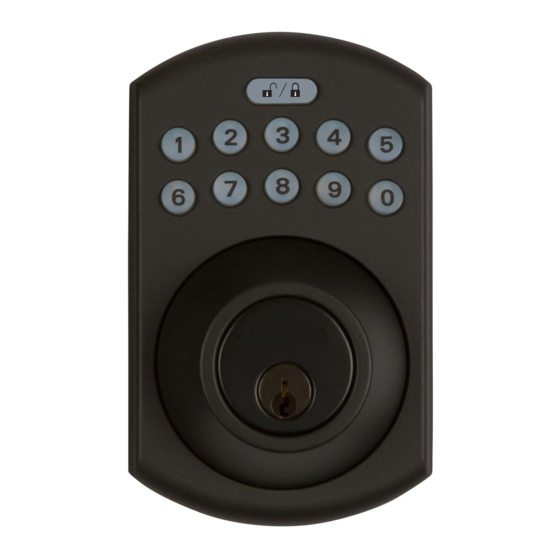
- Page 3 FGS- PL1- Default programming code (PC): 0000 Create a One-Time User Code 4–10 Digits Long Default user code (UC): 1234 ELECTRONIC DEADBOLT Enter Your new programming code (PC) ____________ Enter PC One Time Code Your new user code (UC) ___________________ User Guide The same programming code and user code cannot be accepted.
Need help?
Do you have a question about the MLK1458BK and is the answer not in the manual?
Questions and answers