Table of Contents
Advertisement
Quick Links
Advertisement
Table of Contents

Summary of Contents for Fancom AURA 37
- Page 2 N.B.: The original, authentic version of this manual is the English version produced by Fancom B.V. or one of its daughter companies (referred to further as Fancom). Any modifications introduced to this manual by third parties have neither been checked nor approved by Fancom. Modifications are taken by Fancom to include translations into languages other than English and the insertion and/or deletion of text and/or illustrations to/from the original contents.
-
Page 3: Table Of Contents
Installing the Aura 37 ..........................18 Determine location ........................18 Mount the Aura 37 ........................18 Connect the Aura 37 ........................19 Connect the Aura 37 to FNet ......................20 Installer settings ............................21 CFG .............................. 21 SYS .............................. 22 INF .............................. -
Page 4: Fancom Sales & Service Center
This manual supplies information about connecting and configuring the control computer and information about working with the control computer after installation. Always keep the manual close to the control computer. For more information about the principles of climate management see the Fancom climate handbook. The following symbols are used in this manual: Tips and suggestions. - Page 5 The guarantee does not apply if this product is installed in any other way than is indicated by Fancom and changes have been made to the product.
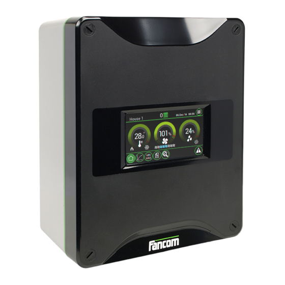
- Page 6 Aura 37 Aura 37 The Aura 37 is a control designed for mechanically ventilated poultry houses with a constant (non-growing animals) or an increasing ventilation demand (growing animals). The Aura 37 has the following features: Ventilation temperature control based on setpoint house ...
-
Page 7: Using The Aura 37
Aura 37 Using the Aura 37 This chapter describes the main parts and the operation of the Aura 37. The Aura 37 can be operated on the touch screen. Touch screen The controller is automatically activated as soon as you switch on the power. The start-up progress is shown on... - Page 8 Aura 37 Using the Aura 37 The Aura 37 screens are divided in three sections: Title bar: Displays the name of the control computer, daynumber and date and time field. The button in the right corner can be used to switch between user and installer views.
-
Page 9: User Settings
Aura 37 User settings The Aura 37 displays the Overview screen by default. This screen provides the temperature, ventilation and relative humidity dials. Temperature dial Readout of the temperature values (°C/°F) in the section. Lower boundary of the comfort zone... - Page 10 Aura 37 User settings Readout of the ventilation status (8 combi fans) (Blue ON / Grey OFF). Readout of the relative humidity status (Blue ON / Grey OFF). Use the dials as follows: Tap the dial you want to set. A pop up of the dial appears: Set the value by tapping ...
- Page 11 Aura 37 User settings Setting the start temperature ventilation (setpoint house). Setting the end temperature ventilation. Setting the setpoint cooling. Setpoint heating and Setpoint cooling can be linked to the Setpoint house temperature. The ventilation control ensures there is always a settable minimum amount of fresh air. If the temperature in the house becomes too high, the controller will provide extra ventilation.
- Page 12 Aura 37 User settings The relative humidity control ensures there is always a settable minimum humdity percentage. If the relative humidity in the house becomes too low, the controller will provide extra moisture. Dial Setting of the relative humidty setpoint.
- Page 13 The day number is a counter increased by the controller each day at midnight by one up to a maximum of 999. If the day number is 0 it will not change. The Aura 37 then controls without the curve, even if the bending points have been set.
-
Page 14: Registration
Aura 37 User settings Readout of the highest, actual and lowest measured temperatures of temperature sensor 1. Followed by the time of measurement. Readout of the highest, actual and lowest measured temperatures of temperature sensor 2. Followed by the time of measurement. - Page 15 Aura 37 User settings Readout of the registration of the day before yesterday. Readout of the cumulative registration over the entire flock. Readout of the amount of water registered. Readout of the amount of feed registered. Readout of the amount of auxilary registered.
-
Page 16: Alarm
Aura 37 Alarm The Aura 37 displays the alarm overview by pressing . There are two types of alarm: Loud alarm: An active loud alarm sounds a siren, shows an alarm message and a report on the screen. This type of alarm has a high priority. - Page 17 Aura 37 Alarm Alarm messages Temperature alarms Alarm Action Min.house temp. (abs) Minimum alarm Max.house temp. (abs) Check wiring and sensors. Min.house temp. (dif) Check if the heater works properly (if available). Max.house temp. (dif) Check minimum difference alarm settings.
-
Page 18: Alarm Overview
The alarm message states that the alarm has been disabled and is active again. The message will be cleared from the alarm overview. Fancom advises testing the alarm weekly for correct functioning. During the test the control computer will give a loud alarm. - Page 19 Aura 37 Alarm Abs. Maximum alarm If the house temperature is higher than the set Abs. maximum alarm, the control computer will give a maximum temperature alarm. The control computer gives a maximum temperature difference alarm if the house Dif.
-
Page 20: Alarm History
Aura 37 Alarm The control computer gives a minimum temperature difference alarm if the house Dif. Minimum alarm temperature is below: Start temperature ventilation Dif. Minimum alarm. Start temperature ventilation: 20ºC Dif. Minimum alarm: 4ºC Calc. min. alarm limit: 16ºC An alarm will occur if the temperature becomes lower than 16ºC. -
Page 21: Installing The Aura 37
Never mount the Aura 37 in a humid and/or dusty room and certainly not in the room where the animals are present. Mount the Aura 37 at such a height that you can control the Aura 37 easily (eye level) and square on a solid backing. The swivels should be positioned at the bottom. - Page 22 Check that the mains voltage and frequency, for which this computer is suitable, correspond to the mains voltage and frequency on site. Be sure that the Aura 37 is properly grounded. When using metal cable trays, grounding at one point of the tray is recommended.
- Page 23 Control computers 2 and 3 are looped. These looped control computers do not require a terminal resistor. The Fancom Greenlink cable (UTP 1x2x0.8mm, unshielded twisted pair) used to wire the FNET and I/O net. Maximum cable length = 1200 meters.
-
Page 24: Installer Settings
(like all the other connected computers). To avoid peak load on the net by several computers activating simultaneously, Fancom advises always entering a computer number. Computer name Setting of the computer name. - Page 25 Communication FNet is the Fancom Network. Several control computers can be linked via this network. FNet is also used to operate the connected control computers from a PC. Master - Slave Master/Slave setting. If the control computer is included in a network, only one control computer in the network must be set as MASTER.
- Page 26 Aura 37 Installer settings See the book 'Aura Principles of climate management' for more information about the influences. Influence low / high outside temperature on the end temperature ventilation On end temp ventilation Setting if the low / high outside temperature must influence the end temperature...
- Page 27 Aura 37 Installer settings Influence maximum ventilation limitation during cooling Limit maximum Setting if the cooling must influence the maximum ventilation limit (YES / NO). ventilation Max ventilation during Setting of the maximum ventilation percentage during cooling (0 to 100%).
- Page 28 Aura 37 Installer settings Water / Feed / Aux Input type Setting indicating the analog control type (NONE / INPUT). Input number (digital) Readout of the sensor input number. Amount per pulse Setting of the amount that corresponds to one pulse.
- Page 29 Aura 37 Installer settings Heating / cooling Temperature hysteresis Setting of the temperature by which the control computer automatically activates the heating / cooling. This prevents the cooling being activated / deactivated with slight temperature fluctuations. Link setpoint house Setting to link the heating / cooling to the setpoint house. This is normally used for the standard heating / cooling control.
-
Page 30: Cmb
Aura 37 Installer settings In the combi-table the relationship between ventilation and air inlets for the entire ventilation course is entered. Actual Readout of the actual combi values. Exh. Setting of the required exhaust positions (%). 12345678 Setting the relais. -
Page 31: Appendix: Connection Diagram Aura 37
Aura 37 Appendix: Connection diagram Aura 37... - Page 32 Aura 37 Appendix: Connection diagram for alarm...
-
Page 33: Technical Specifications
Plastic housing with screw on lid IP54 Dimensions (l x w x h) 300x240x140mm Weight (unpacked) 3.0kg Ambient climate Operating temperature range 0°C to +40°C Storage temperature range -10°C to +50°C Relative humidity <95%, uncondensed Communication Fancom FNet for inter-communication of computers and PC. -
Page 34: Powerboard Rc-Rel13
Aura 37 Technical specifications Aura board Powerboard FC- REL13 Powerboard RC- REL13... - Page 35 Aura 37 Technical specifications IO Net - IO Net + Fnet 1- Fnet 1+ Fnet 2- Fnet 2+ SD Card...
-
Page 36: Appendix: Eg-Declaration Of Compliance
Aura 37 Appendix: EG-declaration of compliance Manufacturer Fancom B.V. Address: Industrieterrein 34 Place: Panningen (the Netherlands) Hereby declares that: Aura 37 Satisfies the conditions of: The Low Voltage Directive 2014/35/EU according to EN-61010 the EMC Guideline, directive 2014/30/EU Emission and immunity according to NEN-EN-IEC 61326...
Need help?
Do you have a question about the AURA 37 and is the answer not in the manual?
Questions and answers