
Related Manuals for SamplexPower MSK-20A

Summary of Contents for SamplexPower MSK-20A
- Page 1 Solar Owner's Please read this manual BEFORE Manual Charge using your Controller Charge Controller MSK-20A...
-
Page 2: Table Of Contents
OWNER'S MANUAL | Index SECTION 1 Safety Instructions ..............3 SECTION 2 General Information, Features & Layout ....... 5 SECTION 3 Installation ................7 SECTION 4 Operation ................ 13 SECTION 5 Protections & Troubleshooting ........... 18 SECTION 6 Specifications ..............23 SECTION 7 Warranty ................ -
Page 3: Safety Instructions
SECTION 1 | Safety Instructions IMPORTANT SAFETY INSTRUCTIONS PLEASE READ THE FOLLOWING SAFETY INSTRUCTIONS BEFORE USING THE CHARGE CONTROLLER. FAILURE TO ABIDE BY THE RECOMMENDATIONS MAY CAUSE PERSONAL INJURY / DAMAGE TO THE CONTROLLER. The following safety symbols will be used in this manual to highlight safety and information: WARNING! Indicates possibility of physical harm to the user in case of non-compliance. - Page 4 SECTION 1 | Safety Instructions 13. Batteries generate Hydrogen and Oxygen during charging resulting in evolution of explosive gas mixture in non-sealed batteries. Care should be taken to ventilate the battery area when non-sealed batteries are used and follow battery manufacturer’s recommendations. 14.
-
Page 5: General Information, Features & Layout
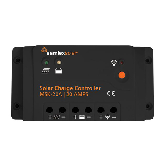
& Layout 2.1 GENERAL INFORMATION MSK-20A is a 20A rated, Series Type of PWM (Pulse Width Modulation) Charge Controller. It is based on an advanced design using a microcontroller for digital accuracy and fully automatic operation. It is designed to charge 12V / 24V Lead Acid Batteries.. - Page 6 NOTES: 1. If the Remote Battery Temperature Sensor is short-circuited or damaged, the control- ler will charge or discharge at the default temperature setting of 25°C. 2. All terminal can accept conductor size up to AWG#8 / 10mm Fig 2.1: Layout of Charge Controller MSK-20A 6 | SAMLEX AMERICA INC.
-
Page 7: Installation
SECTION 3 | Installation 3.1 SAFETY WARNING! CAUTION! PLEASE READ ALL THE SAFETY INSTRUCTIONS GIVEN IN SECTION 1 BEFORE INSTALLING AND OPERATING THE CONTROLLER. FAILURE TO ABIDE BY THE RECOMMENDATIONS MAY CAUSE PERSONAL INJURY / DAMAGE TO THE KIT. DO NOT USE THE UNIT IN WET ENVIRONMENT •... - Page 8 81.4 Solar Charge Controller MSK-20A | 20 AMPS 159.6 Fig 3.1: Dimensional Drawing of Charge Controller MSK-20A 3.3 MOUNTING Refer to Fig 3.1 When mounting the controller, ensure free air through the ventilation slots at the bottom of the unit. There should be at least 6 inches (150 mm) of clearance above and below the controller to allow for cooling.
- Page 9 Place the controller on the surface and align the mounting holes with the drilled holes in Step 3.3.4. Secure the controller in place using 4, #8 self tapping screws. 3.4 CONNECTIONS Solar Panel or Array MSK-20A Temp. Sensor NOTE: Maximum current on the Load Terminals should be limited to 20A...
- Page 10 SECTION 3 | Installation 3.4.1 Step1: Battery Connection WARNING! RISK OF EXPLOSION OR FIRE! NEVER SHORT CIRCUIT BATTERY POSITIVE (+) AND NEGATIVE (-). MISE EN GARDE! RISQUE D'EXPLOSION OU D'INCENDIE! NE COURT-CIRCUITEZ JAMAIS LA BATTERIE POSITIF (+) ET NÉGATIF (-). Refer to Fig 3.2 Before the battery is connected: •...
- Page 11 SECTION 3 | Installation MISE EN GARDE! LA SORTIE DE COURANT SUR LES BORNES DE CHARGE EST LIMITÉE À UN MAXIMUM DE 20A. SI DES CHARGES PLUS LOURDES TIRENT PLUS DE 20A COMME UN ONDULEUR, ETC. DOIVENT ÊTRE ALIMENTÉS, CONNECTEZ-LES DIRECTEMENT À...
- Page 12 SECTION 3 | Installation in overcharging if charger voltage is not compensated. Battery manufacturers, therefore, specify battery charging / discharging voltages and capacities of Lead Acid Batteries at Standard Room Temperature of 25º C. 3.4.4.2 When the battery electrolyte temperature varies from the Standard Room Temperature of 25º...
-
Page 13: Operation
4.1 PRINCIPLE OF OPERATION OF SOLAR CHARGING WITH SERIES TYPE PULSE WIDTH MODULATION (PWM) CONTROL The design and operation of MSK-20A is based on Series Type PWM (Pulse Width Modulation) control at PWM frequency of 25 Hz. 4.2 PWM EXPLANATION The output of the Solar Panel(s)/ Array is connected to the battery in series with a Mosfet Switch inside the controller. - Page 14 At lower frequencies, the rise times of the charging pulses are lower which results in higher gas bubble formation resulting in lowering of active surface area and increase of internal impedance. In MSK-20A, frequency of 25 Hz is used for optimum charging performance. 4.3.2 Benefits of pulsing nature of charging current during PWM During PWM voltage regulated stages of Absorption, and Float Duty Cycle is lower and the charging current is in the form of pulses.
- Page 15 SECTION 4 | Operation 4.4.1.1 Stage 1 - Bulk Stage Please refer to Fig 4.1 This is almost a constant current stage. During this stage, the Mosfet Switch is kept at 100% Duty Cycle (ON continuously) and hence, maximum current equal to the available instantaneous Short Circuit Current "Isc"...
- Page 16 SECTION 4 | Operation 4.4.1.3.1 Automatic Exit from Float Stage to Absorption Stage The charger will exit Float Stage and enter Absorption Stage (Section 4.4.1.2) automatically as follows: (i) During Float Stage, if the load current is more than the current supplied by the Solar Panel(s), the battery voltage will drop.
- Page 17 SECTION 4 | Operation TABLE 4.1 LED INDICATIONS FOR OPERATIONAL STATUS Location of LED Color LED Lighting (Fig 2.1) Function of LED of LED Pattern Operational Status On Steady Battery power to Load Terminals is ON Load Status LED Battery power to Load Terminals is OFF Overload on the Load Terminals.
-
Page 18: Protections & Troubleshooting
SECTION 5 | Protections & Troubleshooting 5.1 PROTECTIONS 5.1.1 Over Current of Solar Panel / Array If the output current of the solar panel / array exceeds 20A rating of the controller, the charging current will be limited to the rated current of 20A. 5.1.2 Short Circuit of Solar Panel / Array If solar panel / array is short circuited, remove the short circuit to resume normal operation automatically. - Page 19 SECTION 5 | Protections & Troubleshooting 4. After 15 sec., the load will be reconnected. If the short circuit condition continues, the load will be disconnected immediately and the Red Load Status LED (3, Fig 2.1) will continue to fast blink @ 4Hz for 20 sec. 5.
- Page 20 SECTION 5 | Protections & Troubleshooting 5.1.10 Low Voltage - Load Disconnect At battery voltage of 11.1/22.2V, the load connected to Load Terminals (6A, 6B in Fig 2.1) will be disconnected. Battery Status LED (2, Fig 2.1) will be Steady Red. Automatic reset at 12.6/25.2V. (NOTE: Loads directly connected to the battery will continue to discharge the battery.) 5.1.11 Over Temperature Protection –...
- Page 21 SECTION 5 | Protections & Troubleshooting 5.2 TROUBLESHOOTING Troubleshooting Guide is shown at Table 5.1. Please refer to LED indications at Section 4.7, Table 4.1 for supplementary information. TABLE 5.1 TROUBLESHOOTING GUIDE Symptom Possible Cause Remarks / Remedy Solar Panel Status LED •...
- Page 22 SECTION 5 | Protections & Troubleshooting TABLE 5.1 TROUBLESHOOTING GUIDE Symptom Possible Cause Remarks / Remedy Battery Status LED (2. Fig Battery temperature has ex- Refer to Section 3.4.4 2.1) is slow blinking Red ceeded 65°C (1 Hz) NOTES: • When battery sensing is being done 1.
-
Page 23: Specifications
SECTION 6 | Specifications 6.1 GENERAL PARAMETER SPECIFICATIONS CHARGE CONTROLLER Type of Charging Control Series Type, PWM control, PWM Frequency: 25Hz Battery Type Factory preset for Sealed Lead Acid (AGM) 12V / 24V Nominal; Auto Sensing Battery System Voltage (<18V sensed as 12V / >18V sensed as 24V) Working Voltage Range of Charge Controller 8V to 32V Rated Battery Charging Current... - Page 24 SECTION 6 | Specifications PARAMETER SPECIFICATIONS INPUT / OUTPUT CONNECTIONS Type of connectors Moving Cage Type for Up to AWG #8 / 10mm wire size PROTECTIONS Solar panel over current; solar panel short circuit; solar panel reverse polarity; Battery reverse polarity; Battery Protections over voltage;...
-
Page 25: Warranty
Warranty 2 YEAR LIMITED WARRANTY MSK-20A Solar Charge Controller manufactured by Samlex America Inc. (the “Warrantor“) are warranted to be free from defects in workmanship and materials under normal use and service. The warranty period is 2 years for the United States and Canada, and is in effect from the date of purchase by the user (the “Purchaser“). - Page 26 Notes 26 | SAMLEX AMERICA INC.
- Page 27 Notes SAMLEX AMERICA INC. | 27...
- Page 28 Ph: 1 800 561 5885 Fax: 1 888 814 5210 Local Numbers Ph: 604 525 3836 Fax: 604 525 5221 Website www.samlexamerica.com USA Shipping Warehouses Kent, WA Plymouth, MI Canadian Shipping Warehouse Richmond, BC Email purchase orders to orders@samlexamerica.com 11023-MSK-20A-1121...
Need help?
Do you have a question about the MSK-20A and is the answer not in the manual?
Questions and answers