Table of Contents
Advertisement
Quick Links
Advertisement
Table of Contents

Related Manuals for technoac SUCCESS AG-309.15N


Summary of Contents for technoac SUCCESS AG-309.15N
-
Page 2: Table Of Contents
DEVELOPMENT, MANUFACTURING AND SUPPLY OF INSTRUMENTATION www.technoac.com Table of Contents 10.1. The work with the receiver in the mode Introduction..........3 «Selection of the cable from a bunch» ..32 1. Appearnce of Receiver......4 10.2. «Hot» keys for the work in the mode 2. -
Page 3: Introduction
The. electrical. signals. induced. in. the. receiver. sensors. are. amplified,. . filtered,.processed.by.the.processor.and.then.displayed.on.the.graphical.display.in.the.form.of. the. utility’s. position. line,. linear. scale,. digital. value. of. the. signal. level. amplification. coefficient,. distance.to.the.communication.axis,.the.value.of.the.current.flowing.through.it,.the.graphic.of.the. signal.level.change.and.other.parameters. Due.to.constant.improvement.of.produced.instruments,.Technoac.LLC.reserves.the.right. to.change. schematics,. software. and. user. manuals,.without. degradation.of. performance. characteristics.for.its.devices,.without.preliminary.notification..Separate.changes.in.user. manual.content.may.be.implemented.after.its.reissue. Up-to-date information about all produced instruments is published on www.technoac.com... -
Page 4: Appearnce Of Receiver
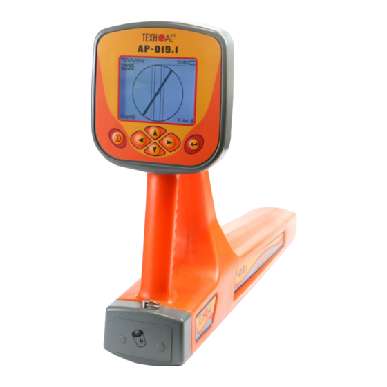
DEVELOPMENT, MANUFACTURING AND SUPPLY OF INSTRUMENTATION www.technoac.com 1. Appearance, AP-019.1 receiver controls AP-019.1.receiver.is.made.in.the.solid.cast.IP54.body.to.the.battery.compartment.the.body. provides.the.protection.IP68,.the.device.can.be.splitted.in.three.components:.the.face.panel.with. controls. and. displays,. battery. compartment. and. bottom. part. with. the. antenna. block.. There. is. external.sensor.connection.port.on.the.back.side.of.receiver. A.graphical.display.with. the.lighting Six-button keyboard Built-in.sound.transmitter A.slot.for.connection.of.the. external.sensors Battery.compartment.for. four.batteries.«type.C» Сonnection.of.external..sensors. A.module.for.omnidirected. -
Page 5: Operating Modes
DEVELOPMENT, MANUFACTURING AND SUPPLY OF INSTRUMENTATION www.technoac.com 2. OPERATING MODES 2.1 “Route” mode When.turning.on.the.receiver.for.the.first.time,.the.device.will.begin.in.route.mode.and.the.service. information.will.appear..Route.mode.is.the.primary.screen..Below,.the.indications.are.shown,.which. are.dependent.on.the.operator.position.near.the.located.utility. .Position.of.utility.axis.shows,. The.receiver.can’t.detect.the.utility. The.ball.on.the.screen.shows. where.the.utility.is.situated. the.direction.in.which.utility. is.located. Depth.and.current.measurement. When.approaching.the.utility,. When.above.the.utility,.a.solid.line. enable.automatically,.If.the.utility. a.blurred.line.indicates.its.position. will.appear.which.is.perpendicular. indicating.line.is.aligned. to.the.utility’s.direction.. with.the.axis.of.the.receiver. Route Mode Description Frequency.of. Type.of.incoming.signal. Amplification.coefficient. the.enabled.filter (continuous.or.pulse) in.dB Battery.charge.level... -
Page 6: Graphic Mode
DEVELOPMENT, MANUFACTURING AND SUPPLY OF INSTRUMENTATION www.technoac.com Route Mode and Depth Measurement When. the. operator. stands. strictly. . Receiver.and.utility. above.the.utility.and.the.line.indicating. . axis.are.perfectly. the.utility..is..positioned.strictly..in..the. . aligned centre..field..between.the.two..dotted. . lines,.an.automatic.depth.and.current. Buried.depth. measurement.is.performed.. of.the.utility NOTE: When. performing. a. depth. measurement,.the.receiver..antenna. Current. should.be.positioned.perpendicularly. of.the.utility to.the.utility.. -
Page 7: Minimum Maximum
DEVELOPMENT, MANUFACTURING AND SUPPLY OF INSTRUMENTATION www.technoac.com 2.4 “Minimum maximum” In.“MIN.&.MAX”.mode,.the.receiver.screen.is.split.into.two.segments..The.upper.segment.is.a. moving.diagram..which.represents..signal..level..changes..according..to.the.“minimum”..method. . –..it..means..that..the.signal.will.be.minimal.when.the.receiver.is.positioned.strictly.over.the.utility..If. the.receiver.is.moved.aside,.the.signal.level.will.increase... The.lower.segment..represents.the.“maximum”..method..diagram..–..the..signal..will..be..maximal. . if..the..receiver.is.positioned.strictly.over.the.utility,.and.it.will.decrease.if.the.device.is.moved.further. away. ..This.mode.does.not.allow.depth.and.current.measurements.. Quick.change.of.lower.sensor. Type.of.incoming. operation.mode Frequency.filter signal. (continuous.or.pulse) Battery.charge.level Indication.of.lower. Amplification.coefficient.in.dB sensor.operation.(Filter,. Broadband,.Radio) Quick.change.of.diagram.scale Digit,.representing. current.(far.right).value Every.time.image.is.refreshed,. of.the.graph.in.percentage. the.graph.moves.1.position.left. terms and.far.right.position.is.filled.with. new.measurement.value 2.5 Modes with Graphic Representation of “Relative distance to the... -
Page 8: R.dis. Graph" Mode
DEVELOPMENT, MANUFACTURING AND SUPPLY OF INSTRUMENTATION www.technoac.com This.parameter.can.have.values.from.“0.01”.to.“30.00”,.“>30”.and.“∞”..Value.“∞”.are.indicated. when.the.receiver.is.positioned.aside.from.the.utility.or.when.the.utility.is.positioned.above.the.receiver. (an.example.being.when.there.are.overhead.voltage.lines.around)..The.parameter.“relative.distance. to.the.utility”..will..have..its..minimum..value..when.the..receiver..is..positioned.directly.above.the..utility. . axis...In..this..case,..this..value..is.equal.to.the.real.burial.depth.of.the.utility... Minimum.value.of.the. parameter.-.2.40..is.equal.to. real.burial.depth.of.utility. Utility The.receiver.has.two.modes.with.indication.of.“relative.distance.to.the.utility”:. “R.dis. Graph” is. used.when.the..“relative..distance..to..the.utility”..graph..and..utility..route..are..indicated..simultaneously,. whilst. the. “MIN&R.Dist mode“ is. used. when. screen. of. the. receiver. indicates. 2. graphs. (minimal. signal.and.“relative.distance.to.the.utility”)..2.5.1 “R.dis. Graph” mode This.mode.is.the.same.as.“Graph”.mode..The.screen.is.split.in.two.parts,.an.upper.display. -
Page 9: Min&R.dist" Mode
DEVELOPMENT, MANUFACTURING AND SUPPLY OF INSTRUMENTATION www.technoac.com When.two.utilities.are.buried.close.to.each.other.while.moving.the.receiver.straight.across.the. . utility.axis.in.“R.dist”.mode,.an.operator.will.be.able.to.see.the.indication.shown.below: Minimal.values.of.“relative.distance.to.the.utility”.indicate.the.presence.of.the.utility.with.some. . fault.because..in.the..case..of..multiple..utilities..laying..nearby,..minimum..signal..point..may..move. . due..to..coinfluence.of.the.signals. You.can..enable.the.“R.dis.Graph” mode..from..“Route”..mode..by..pressing.the.“>”..button.or. by.switching.it.in.the.“Modes”.section.of.the.receiver’s.main.menu. 2.5.2 “MIN & R.Dist” Mode In.this.mode.the.screen.is.split.in.two.parts...Upper.part:.Minimal.signal.graph,.lower.part:.“relative. distance.to.the.utility”.graph.in.real.time.. Digit.indicates.the.minimum. Hint.–.change.of.graph. signal.level.of.far.right.point.of.the. scale.in.2,.4.and.8.times. display by.pressing.“up”.and. “down”.arrows Digit.indicates.relative.distance. value.of.far.right.part.of.the. “R.dist”.value.indicated.by. display “∞”.icon You.can.enable.“MIN.&.R.Dist”.mode.only.from.“Modes”.section.of.main.menu. 2.6 “2 Frequencies” Mode Window In.the.“2.frequencies”.mode,.the.cable.condition.and.pipeline.protection.diagnostic.is.performed. - Page 10 DEVELOPMENT, MANUFACTURING AND SUPPLY OF INSTRUMENTATION www.technoac.com IMPORTANT NOTE: Modes are split in two sets: basic and extended. In basic set, only 3 modes are available: “Route”,“Graph” and“R.dis.graph”. All modes are available in extended set: “Route”, “Graph”, “Graph+”, “MIN & MAX”, “2 Frequency”, “R.dis.graph” and “MIN&R.dist.”.
-
Page 11: Receiver Menu Description
DEVELOPMENT, MANUFACTURING AND SUPPLY OF INSTRUMENTATION www.technoac.com 3. Receiver menu description 3.1 Receiver switching on and menu call To.switch.on.the. Press.«Enter». receiver.press. button.to. the.button open.the. «Power» Menu 3.2 The general view of the menu screen menu.option.name. The.selected.menu. brief.menu.option. option.is.highlighted.with. description the.dotted.line,.flashes. - Page 12 DEVELOPMENT, MANUFACTURING AND SUPPLY OF INSTRUMENTATION www.technoac.com Thirteen.items.of.menu.contain.parameters.of.setting,.which.are.opened.in.the.panel.located.in.the. upper.part.of.the.indicator. Table 1 Item of the № Display image Parameter description menu The.working.frequency.of.the.receiver. Filter It.is.selected.from.the.set: 50(60) Hz, 100(120) Hz, 512 Hz, 1024 Hz, 8192 Hz 32768 Hz. The.amplification.coefficient.of.the.scaling. amplifier.can.be.changed.from.0 dB to 80 dB.
- Page 13 DEVELOPMENT, MANUFACTURING AND SUPPLY OF INSTRUMENTATION www.technoac.com Base Set of modes: Mode -.«Route».(2D.display.of.the.location.of.the. route.cable; Base Mode -.«Graph».(visually.represents.the.changes. of.signal.level.of.surveyed.cable); Аdvanced Mode Advanced mode: -.«Graph+» (this.mode.combines.two.previous. modes. and. allows. to. locate. two. cables. simultaneously:.one.on.50Hz,.and.the.other.on. freqency.set..by.transmitter.z);...
- Page 14 DEVELOPMENT, MANUFACTURING AND SUPPLY OF INSTRUMENTATION www.technoac.com Advanced mode: Advanced Modes -. «MIN&MAX». (graph. representation. of. minimum.and.maximum.signals) Advanced mode: Advanced Modes «2. frequency». (simultaneous. operation. in. two. frequencies,.also.know.as.frend-or-foe.mode). Sound Switching.on./.switching.off.of.sound. notifications.the.created.by.the.built-in.speaker. This.menu.is.opened.in.the.main.field.of.an. indicator. Language <Russian/English> Locale.of.the.device Settings System of units <Meter/Foot>...
- Page 15 DEVELOPMENT, MANUFACTURING AND SUPPLY OF INSTRUMENTATION www.technoac.com Sound of keys <ON/OFF> Disables.keys.sound <1.sec/2.sec/.3.sec/.4.sec/5. Delay of menu sec> Time-out.before.closing.the.menu.when.no. buttons.are.pressed. •.Popup hints <ON/OFF> Disables.pop-ups.with.useful.hints. • Reset <Reset> Settings osettings Resets.the.receiver.to.factory.settings...
-
Page 16: Start Of Work
DEVELOPMENT, MANUFACTURING AND SUPPLY OF INSTRUMENTATION www.technoac.com 4. Start of work If alkaline batteries are used -.Before.start.of.work,.you.should.install.the.batteries.into.the. corresponding.compartment.of.the.receiver.in.the.following.sequence: Unsnap.Battery. Install.the.batteries,. Install.four.new.elements.into. the.battery.compartment.of.the. compartment..Pull.out.the. observing.the.polarity ring.on.the.receiver.handle. device,.minding.polarity. Install.the.battery.compartment. into.the.body.until.it.snaps. Receiver switching To.switch.on.the.receiver,.press.the.“Power”.button The.indication.of.the.Firmware.version,.manufacturer.logo.and. . . device.name.will.appear.on.the.screen. Then,.the.receiver.will.automatically.enter.into.“Route”.mode. in.5.seconds..When.first.switching,.the.factory.settings.are.set.by. . default...The.filter.frequency.is.50.Hz. A.description.of..factory..settings..can..be..found..in..the. -
Page 17: Search Of Cables In The Mode "Route
DEVELOPMENT, MANUFACTURING AND SUPPLY OF INSTRUMENTATION www.technoac.com Basic Receiver Functions •.Location.and.tracing.of.underground.utilities.with.depth.measurement.in.“Route”.mode. •.Location.and.tracing.of.utilities.in.“Graph”,.“Graph+”,.and.“MIN.&.MAX”.modes. •.Tracing.of.non-metal.utilities.in.“Sonde”.mode. •.Saving.of.coordinates.and.parameters.of.located.points. •.Operation.in.“2.Frequency”.mode.(fault.location.and.detection.of.signal.direction). •.Selection.of.the.cable.from.a.bunch.with.inductive.clamp. 5. Search of Utilities in “Route” mode Route. mode. is. the. main. mode. for. route. location. of. various. utilities. (cables. &. pipelines). at. all. -
Page 18: Search Of A Communication And Measurement Of Its Burial Depth
DEVELOPMENT, MANUFACTURING AND SUPPLY OF INSTRUMENTATION www.technoac.com 5.2 Search of a Communication and Measurement of its Burial Depth 1..Come.to.the.supposed.place.of.the.utility.under.the.voltage.or.induced.voltage.in..frequency. 50(60)Hz. 2..If.the.utility.is.far.from.the.operator,.you.will.see.on.the.screen: utility communication 3..When..moving..towards..the..supposed..place..of..the.utility..location,..the..“ball”..will..appear. on.the.screen..It.shows.the.presence.of.a.utility.and.that.it.is.a.significant..distance.from.the. operator... communication utility 4..The..“ball”..position..shows.the.direction.of.the.utility.relative.to.the.operator.. utility 5..When.the.operator.moves.closer.to.the.utility,.the.axis.will.move.to.the.centre.of.the. circle..This.means.that.the.operator.is.standing.directly.over.the.utility utility... - Page 19 DEVELOPMENT, MANUFACTURING AND SUPPLY OF INSTRUMENTATION www.technoac.com The.measurement.of.the.burial.depth.of.utility 7..Further.you.should.rotate. Cable the.device,.until.the.utility.axis. is.aligned.along.the.receiver. axis..In.this.position,.given. ‘f’.(the.current.in.the..cable). is.sufficient,.the.window..will. appear.displaying.its.burial.. depth.and.current..Now,.the.. operator.stands.alongside.the. utility.. In.this.position,.it.is.possible. . indications.of.the. to.move.forward.and.trace. indications.of.the.burial. current a.whole.cable). depth Power.cables.most.frequently.lay.at.a.depth.of.60-80.cm,.allowing.to.differ.them.from. . pipelines...It..is..possible..that.a.cable..lays..in..one..channel..with.a.pipeline,..when..the..burial. . depth.can.significantly.exceed.1.metre.. If.the.communication.axis.cannot.be.located.exactly.in.the.limited.area,.and.the.periodical. . jumps. are. happening. from. one. border. to. the. other,. it. indicates. the. presence. of. several. .
-
Page 20: Cable Route Location In The Active Mode
DEVELOPMENT, MANUFACTURING AND SUPPLY OF INSTRUMENTATION www.technoac.com 5.3 Cable Route Location in the Active Mode This.mode.is.used.for.the.location.and.tracing.of.electro-conducting.underground.utilities.(power. cables,. optic. fibre. cables. with. metal. armouring. and. pipelines). by. using. the. signal. transmitter.. . Tracing.is.possible.at.the.following.frequencies:.512, 1024, 8192 and 32768 Hz. The.filter.on.the.receiver.is.set.manually.in.accordance.with.the.selected.generator.frequency. When.locating.the.cable.route.in.the.conditions.of.the.large.number.of.surrounding.utilities,. . - Page 21 DEVELOPMENT, MANUFACTURING AND SUPPLY OF INSTRUMENTATION www.technoac.com Procedure for search of communication and conduction of cable route location 1.. Connect. . the. . transmitter. . 2..Turn.on.the.transmitter..Set..the.signal.type.-. to. . the. utility. by. . contact. . or. impulse.“Co”/continuous.“Pu” / pulse.. contactless.method. The.generation.frequency.on.the.transmitter.-.512,.
-
Page 22: Graphic
DEVELOPMENT, MANUFACTURING AND SUPPLY OF INSTRUMENTATION www.technoac.com Press. “Enter”. again.to. return.to. To.confirm. main.menu your. Press. Select. selection. “Enter”. “Signal”.in. press. again.to. buttons the.menu buttons “Enter”. return.to. Select.the. button main.menu type.of.signal View of the Receiver Screen for Route Location in the Active Mode The.input.signal.type.set.in.the.receiver. -
Page 23: Setting Of The Receiver For Work In The
DEVELOPMENT, MANUFACTURING AND SUPPLY OF INSTRUMENTATION www.technoac.com 6. Search of Utilities in “Graph” Mode The. “Graph”. mode. is. the. support. . mode. . and. is. able. to. locate. various. utilities. (cables. and. . pipelines),..both..in..the..passive..and..active..modes..with..the..route..locating..transmitter...In. . passive..mode,.the..cable..location..is..carried..out..at..frequencies.of.50(60) and 100(120)Hz and..in..the..active.mode.- 512,1024, 8192 and 32768 Hz. The.“Graph” mode.can.be.used.to. - Page 24 DEVELOPMENT, MANUFACTURING AND SUPPLY OF INSTRUMENTATION www.technoac.com In.the.“Graph”.mode.the.work.is.performed.in.the.“Continuous”.or.“Impulse”.signal..The. difference.at.the.work.with.the.“Impulse”.signal.is.in.that.the.digit.in.the.center.of.the.analogue. scale. shows. not. the. current. value. of. the. signal,. but. the. maximum. value. (amplitude). of. the. transmissions.of.the.interruptible.signal.from.the.route.locating.transmitter..The.pitch.of.the.tone. of.the.sound.synthesized.also.corresponds.to.the.maximum.value.of.the.signal.for.the.period.of. the.impulse.transmitted. Press. “Enter”. again.to. return. To.confirm. to.main. Press. your. menu. Select. Select.the. “Enter”.
-
Page 25: Mode
DEVELOPMENT, MANUFACTURING AND SUPPLY OF INSTRUMENTATION www.technoac.com The change of the input signal amplification coefficient should be performed manually by short pressing buttons or semi-automatically by holding one of them pressed for 1 sec. In.the.“Graphic”.mode.it.is.possible.to.listen.synthesized.sound.through.the.built-in.speaker,. The.sound.tone.pitch.changes.depending.on.the.signal.level.. Press. To.confirm. “Enter”. your. -
Page 26: Search Of Communications In The Mode "Graphic
DEVELOPMENT, MANUFACTURING AND SUPPLY OF INSTRUMENTATION www.technoac.com 6.3. Search of Utilities in “Graph” Mode 1..Perform.the.receiver.setting.-.select.the.Graphic.mode 2..Locate.the.receiver.in.parallel.to.the.supposed.axis.of.the.utility,.slowly.move.in.the.direction,. as.shown.in.the.figure.below.. 3..Slowly.move.the.receiver.towards.the.area.where.you.previously.experienced.problems.locating. the.utility..You.can.see.the.example.of.operation.on.this.picture: Сommunication operator.movement. direction In.the.presence.of.two.utilities,.the.approximate.view.of.the.graphic.on.the.receiver.screen.is. shown.in.the.figure. Сommunication1 Сommunication2 operator.movement. direction Graphic.on.the.receiver. screen 4..You.should.locate.the.utility.by.the.maximum.signal.level.. -
Page 27: Search Of The Utilities In The Mode " Graphic
DEVELOPMENT, MANUFACTURING AND SUPPLY OF INSTRUMENTATION www.technoac.com 7. Search of Utilities in “Graph+” Mode The..“Graph+”..mode..is..available..in..the..advanced..set..of..modes..“Graph+”..is..the..auxiliary. mode...This.mode.differs.from.the.mode.“Graph”,.as.it.shows.a.“2D”.image.compatible.with.the. graphic,.not.the.relative.position.of.the.route,.but.automatically.demonstrates.the.presence.and. provision.of.the.near.“power”.cable.under.the.voltage.with.the.frequency.50(60).Hz. 7.1 Setting of the Receiver for Work in the “Graph+” Mode The..setting..of..the.receiver..and..use..of..the..“hot..keys”..for..work..in..the..mode..“Graph+”...fully. . matches.with.the.setting.of.the.receiver.for.the.“Graph”.mode.(see.sections.7.1.and.7.2). 7.2 Search of Utilities in the “Graph+” Mode 1..1.. - Page 28 DEVELOPMENT, MANUFACTURING AND SUPPLY OF INSTRUMENTATION www.technoac.com 5.. Approach.the.supposed.place.of.cable.route,.on.which.the.signal.from.the.generator.was. . transmitted..Locate.the.receiver.axis.in.parallel.to.the.utility.axis.. The.graph.showing.the.change.in.the.signal.level.will.be.displayed.on.the.screen.in.frequency. 1.kHz,..on.the.2D.image.of.the.route.of.the.cable.located.near.(if.any).will.be.displayed.under.the. voltage.50(60)Hz. You.should.move.the.receiver.as.shown.on.the.figure. Cable.under.voltage..50(60).Hz operator.movement. direction cables.with.the.induced. signal.1,0kHz.from.the. generator The.place.of.the.crossing.of.the.cable.corresponds.to.the.setting.of.the.pointer.“50.Hz”.onto. the.centre.of.the.circle.at.maximum.value.of.the.indication.on.the.“Graph”.of.the.active.frequency. signal.. Utility.axis.“50.Hz”.. is.in.the.centre Utility.axis.“1..kHz” .is.determined. on.the..maximum.level. of.the.signal..on.the.graphic...
-
Page 29: Perfoming The Cable Location In The Mode "Min & Max
DEVELOPMENT, MANUFACTURING AND SUPPLY OF INSTRUMENTATION www.technoac.com 8. Performing a Cable Location in the Mode “MIN & MAX” In.the.mode “MIN & MAX”,.the.device.works.simultaneously.both.on.the.method.“maximum”..and. the.method.“minimum”..This.mode.is.used.in.the.conditions.of.distorted.field,.in.the.presence..of..nearby. . utilities.and.at..the.low..induced.signal..It..allows.the.user.to..perform..location.and.to..determine.the. presence.and.location.of.utilities.located.nearby.. In.the “MIN & MAX” mode,.the.receiver.display.is.divided.in.two.halves..The.moving.diagram..of..the. . signal..level..change..is..displayed..in..the..upper..part..by..the. “minimum”.method..-..when..located. over.the.cable,.the.signal.is.minimal,.and.when.deviating.from.the.axis,.the.signal.increases..The.bottom. half.of.the.screen.shows.the.moving.diagram.of.the.signal.level.change.depending.on.the.time.by.the. . “maximum”..method..-..when..you..stand..over..the..cable,..the..signal..is..maximum,.and.when..deviating. from.the.axis,.the.signal.decreases. In.this.mode,.the.value.of.the.depth.and.current.in.the.utility.are.not.displayed.. -
Page 30: Performing Cable Route Location In The Mode "2 Frequencies
DEVELOPMENT, MANUFACTURING AND SUPPLY OF INSTRUMENTATION www.technoac.com 9. Performing Cable Route Location in “2 Frequencies” Mode The.mode.“2.frequencies”.was.added.so.the.user.could.determine.the.signal..direction.in.cables.. Additional possibilities of the mode are described in App. 2: Append..2.p.3.Amplitude.“two-frequency”.method..“ΔA”; Append..2.p.4.Phase.“two-frequency”.“Δφ” The mode “2 frequencies” is realised only with the contact method of connection of the transmitter. - Page 31 DEVELOPMENT, MANUFACTURING AND SUPPLY OF INSTRUMENTATION www.technoac.com 3..The.signal.from.the.utility,.to.which.the.route. 4..Based.on.the.direction.of.the.. locating.transmitter.is.directly.connected,. “arrow”,.it.is.possible.to.distinct. is.conventionally.named.-.“friend”..The.“parasitic”.. a..“friend”.signal.from.a.“foe”. signal.from.the.nearest.utility,.on.which..the.generator. one,.since..the.current.direction. signal.is.transferred,.in.conventionally..named.as. in.“friend”..utilities.is.opposite.the. “somebody.else’s”... “transferred”.currents.flowing. through.“foe”.utilities.. “friend” “foe” 5..“Signal.direction.-.forward”.is.the.conventional.concept.and.“assigned”.by.the.operator,. for..this..position.of.the.sensor.relative.to.the.route..The..“assignment”..is..performed..by..the. . pressing..of..the..button..“. .”;.when..the..sensor..is..located..exactly..over..the..“allocated” utility.that.is.supposed.to.be.a.“friend”...After.that,.the.pointer.of.the.signal.direction..takes.the. form.–.1. “friend” When.switching.to.the.“foe”.communication.with.the.other.“signal.direction”.(or.at.the.change. . of.the.sensor.position.to.the.“reverse”),.the.sound.will.be.emitted.(if.switched.on).and.the.arrow. . will.show.the.“signal.direction.-.back.1”.. “friend” “foe”...
-
Page 32: The Work Mode "Cable Selection From A Bunch
DEVELOPMENT, MANUFACTURING AND SUPPLY OF INSTRUMENTATION www.technoac.com 10. The work mode «Cable selection from a bunch» The.mode.«Cable.selection.from.a.bunch».is.switched.on.and.off.automatically.with.the.connection. and.disconnection.of.the.external.sensor.(ES) CI-105/110 (inductive.clamps).or. NP-117 .superimposed.frame). The.mode.is.intended.for.selection.of.the.«allocated».cable.from.the.bunch.of.cables.on.the.basis. of. maximum. signal. emitted. by. this. cable.. The. selection. can. be. carried. out. at. all. the. frequencies. - Page 33 DEVELOPMENT, MANUFACTURING AND SUPPLY OF INSTRUMENTATION www.technoac.com Press. ‘Enter’. again.to. return. To.confirm. Press. to.main. your. ‘Enter’. menu. selection. again.to. Select. Select. the. signal. press. return. type.corresponding. «Signal».in. ‘Enter’. to.main. the. signal. the.menu. button. type. from. the. menu. t r a n s m i t t e r ,.
-
Page 34: Hot" Keys For The Work In The Mode "Selection Of The Cable From The Bunch
DEVELOPMENT, MANUFACTURING AND SUPPLY OF INSTRUMENTATION www.technoac.com .«Sound».in. the.window Save parameters of measurement into the memory by pressing the button Alternately.putting.on.«Inductive.clamps».or.applying.a. Cable.1 attachable.frame.to.the.cables.bundle,.find.«isolated».cable. by.the.higher.level.of.the.signal.(Fig..10.5). Cable.2 The.tone.pitch.of.the.synthesised.sound.correspond.to. the.signal.value.(including.and.«impulse».amplitude) Cable.3 compare signals, should perform measurements at the equal amplification coefficient. In the example (fig. 10.5) it is possible to compare values only with the amplification 42 dB. -
Page 35: Mode "Search Of Defects" Using External Sensors
DEVELOPMENT, MANUFACTURING AND SUPPLY OF INSTRUMENTATION www.technoac.com 11. Mode «Search of defects» using external sensors The. mode. ‘Search. of. defects’. is. switched. on. and. off. automatically,. when. connecting. and. disconnecting.external.sensors.DKI-117,.DOLK-117..The.mode.«Search.for.defects».with.external. sensors.DKI-117/DODK-117.was.added.for.search.of.insulation.defects. The.search.of.defects.of.cable.defects.can.be.carried.out.at.all.frequencies.both.in.an.active,.and. passive.modes. 2D.display.of.the.route.location 2.The.graphic.of.time.change.of.the.external.sensor. signal.level The.graphic.can.be.hidden.by.long.pressing.of.the. button.. - Page 36 DEVELOPMENT, MANUFACTURING AND SUPPLY OF INSTRUMENTATION www.technoac.com Preparation of the sensors for work DKI-117 Prepare.the.sensor.for.operation. release.the.slip.pull.out.the.internal.nut.of.the.rod.till.stop tighten.the.slip.nut.of.the. similarly.pull.out.pull.out.the.second.support..internal.rod move.the.rod.to.the.right. till.the.connection.with.the. fixator The. average. position. of. the. fixator. corresponds. to. the. angle. 30,. end. -. angle. 60. (fig.. 11.3).. Maximum.distance.between.electrodes.corresponds.to.the.maximum.sensibility. 3-position.switch.of.the.weakening - in the position «О».-.signal.100%...
- Page 37 DEVELOPMENT, MANUFACTURING AND SUPPLY OF INSTRUMENTATION www.technoac.com DODK-117 The.survey.shall.be.performed.by.two.operators,.the.one.operator.has.the.measuring.electrode,. and.the.second.one.has.the.measuring.electrode.and.receiver..(fig. 11.5)..Based.on.the.receiver. indications,.you.can.locate.the.damaged.cable.(by methods described in the application 2 p.1-2). NOTICE! When working with the sensor DODK, the electrodes should be used without gloves, providing the contact of the sensor with a skin (fig. 11.6) Fig.
- Page 38 DEVELOPMENT, MANUFACTURING AND SUPPLY OF INSTRUMENTATION www.technoac.com call.out To.change.. of.the. the. menu parameter. press selected,. Select.the. Set.the. the.button press.the. working. icon.«Filter». «Enter» Enter.button. frequency,. in.the. for.example,. window. 512.Hz.(*) Wait for several seconds till menu icons disappear The. search. of. insulation. damage.
-
Page 39: Hot" Keys For Work In The "Graphic" Mode With Dodk And Dki
DEVELOPMENT, MANUFACTURING AND SUPPLY OF INSTRUMENTATION www.technoac.com The.user.can.listen.synthesized.sound.through.the.built-in.sound.speaker..The.sound.tone. pitch.changes.depending.on.the.signal.level..The.synthesized.sound.can.be.switched.on.in.the. menu.«Sound». call.out To.exit.the. To.enter.the. setting.of.the. of.the. mode.of.the. parameter,. menu parameter. press.the. press selection,. the.button press.the. the. Select. Select Enter.button. «Enter» button the.icon. necessary «Enter» «Sound».in. Parameter the.window 11.2 «Hot» keys for work in the «Graph» mode with DODK and DKI step-by-step.(by.2dB).decrease./.increase.coefficient.of.the. - Page 40 DEVELOPMENT, MANUFACTURING AND SUPPLY OF INSTRUMENTATION www.technoac.com Appendix 1 Receiver AP-019.1 Specifications Parameter Value Switching.50(60)/.100(120)/.512/.1024/.8192./. Receiver.filter.centre.frequency 32768.Hz «Wide.band»frequency.band 0,04...8.kHz Frequency.range."Radio" 8...40.kHz Maximum.amplification.factor.of.the.electric. 120.dB path Dynamic.range.of.the.input.signal 100.dB Number.of.embedded.sensors Max..Sensitivity .5.mkA.at.1m.distance.(at.33.kHz). Selectivity >100,.stopband.supression.up.to.120.dB -3.dB Sensors.type Inductive Auto.-.for.2D.display.«Route»..Semi-automatic.or. Sensitivity.control manual.(optional).-.for.the.«Graphics»..Automatic. or.manual.(optional).-.for.the.«2F».mode. Determination.the.burial.depth.of.the.route Automatically.in.«Route».mode.0...9,99.m Laying.depth.identification.accuracy...
- Page 41 DEVELOPMENT, MANUFACTURING AND SUPPLY OF INSTRUMENTATION www.technoac.com Appendix 2 Searching methods by АP-019.1 1. MAX method when searching the place of insulation damage with sensors DKI-117 and DODK-117 When.searching.for.insulation.damage.by.«MAX».method,.the.one.of.the.input.terminals.(contact. pins. of. DKI. or. electrodes. of. DODK). should. be. placed. over. the. route,. and. the. second. one. -. at. a.
- Page 42 DEVELOPMENT, MANUFACTURING AND SUPPLY OF INSTRUMENTATION www.technoac.com 2. Method MIN when searching the place of damage location using sensors DKI-117 or DODK-117 When. searching. for. insulation. damages. by. «MIN» method,. the. contact. pins. of. . DKI-117. or. DODK-117.electrodes.should.be.placed.over.the.route,.along.the.axis.of.the.route..When.you. use.the.MIN.method,.the.signal.increases.smoothly.at.first,.then.rapidly.decreases.to.a.certain. minimum.value,.then.as.the.distance.from.the.damage.place.increases,.it.rises.sharply.again.and.
- Page 43 DEVELOPMENT, MANUFACTURING AND SUPPLY OF INSTRUMENTATION www.technoac.com 1. Amplitude “two-frequency” method “ΔA” This.method.was.added.for.contactless.search.of..insulation.defects.of.city.cables.with. resistance.less.than.5.kOhm..The.smaller.the.distance.to.the.end.of.the.cable,.the.higher.the. sensitivity.of.the..method.on.this.site.. The method description:.the.two-frequency.signal.is.transmitted.from.the.generator..The. ratio.of.two-frequency.signal.amplitudes.remains.stable.if.there.is.no.damage.to.the.cable..In.the. presence.of.damage,.the.ratio.of.amplitudes.in.the.place.of.damage.is.changed. Table 8 1..1.. Exit. . output. . of. . the. . 2..The.transmitter.in.the.mode. generator. . should. . be. . “2F”.sends.to.the.utility. connected. . to. . the. . “start”. .
- Page 44 DEVELOPMENT, MANUFACTURING AND SUPPLY OF INSTRUMENTATION www.technoac.com 7...The.sharp.positive.overfall.of.the.“A8/A1”.value.by.3dB.and.more.indicates.the.possibility.of.. defect.existence.(the.resistance.is.less.than.5.kOhm)..The.sensor.should.be.located.straight.. across.the.utility.. If.you.go.through.the.same.site.in.the.opposite.direction.. (towards.the.generator),.holding.the.receiver.the.same.as.. before.with.reset.of.the.indication.(using.the.button. ),.. negative.values.of.the.reading.(more.than.minus.3dB).will.. mean.that.there.is.damage.in.the.cable. 2. Phase “two-frequency” Method “Δφ” The..contactless..method..of..search..for..insulation..defects..of..city..cables..with..resistance. . less..than.10.kOhm..The.smaller.the.distance.from.the.end.of.the.cable,.the.higher.the.sensitivity. of.the..method.on.this.site..This.method.cannot.be.used.in.a.city.because.of.high.distortion.of.the. signal.. Steps.1-3. 4. .. “Δφ”. . shows. the. . change. . of. . the. . phase. .
- Page 45 DEVELOPMENT, MANUFACTURING AND SUPPLY OF INSTRUMENTATION www.technoac.com Appendix 3 Area Survey Before Excavation Works First.of.all,.the.area.should.be.surveyed.with.the.receiver.in.passive.mode,.in.order.to.locate.the. . signal..from..energised..power..cables,..pipes..with..cathodic..protection..or..any..other..current..providing. . utility..To.do.that,.use.the.following.frequencies.consequently:.50.Hz,.100.Hz.,.Radio.and.Broadband. . mode..Area.survey.in.broadband.frequencies.should.be.performed.in.“MIN.&.MAX”.mode,.in.lower. . sensor.mode.WB.(0-8kHz).and.Radio.(over.8kHz). In.this.case,.the.operator.should.rely.on.“MAX”.scale. .At.50.a.100Hz.frequencies.in.Route.mode,.the.signal.strength.will.increase.as.you.are.moving.to. the.utility..The.following.indication.should.appear.on.the.screen.while.performing.these.actions: First.make.sure.that.there.is.no.utility.in.the.centre.of.the.surveyed.area..To.do.that,.the.operator. with.the.receiver.stands.above.the.tested.point.and.the.second.operator.moves.the.transmitter.around. the.first..one..The.radius.should.be.10-20m.and.the.first.operator.should.point.the.head.of.the.receiver. towards.the.second.operator.with.the.antenna..
- Page 46 DEVELOPMENT, MANUFACTURING AND SUPPLY OF INSTRUMENTATION www.technoac.com .If.there.is.no.utility.in.center.point.of.the.area,.then.start.the.general.location.routine.described. below. When.surveying.the.area.in.active.mode,.it.is.necessary.to.place..IEM-301.5.antenna.horizontally. in.the.center.of.the.plot.(you.can.remove.the.antenna.from.its.stand)..In.this.position.the.antenna.will. be.in.the.flatness.parallel.to.all.surrounding.utilities.in.the.area. After.that.it.is.necessary.to.connect.the.antenna.to.the.transmitter.and.start.the.induction..Power. of.the.transmitter.should.be.set.according.to.the.size.of.the.surveyed.area.(the.smaller.the.area.–.the. smaller.the.power). Area.survey.in.active.mode.should.be.carried.out.in.“Graph”.mode.of.receiver.at.the.same.frequency. as. had. been. set. on. the. transmitter.. Operator. should. move. around. the. transmitter. and. perform. to. measurements.at.each.point.in.two.mutually.perpendicular.positions.. The.presence.of.the.utility.will.be.indicated.by.the.“signal.strength”.value.(upper.left.part.of.display). or.the.graph.in.bottom.part.of.the.screen.
- Page 47 DEVELOPMENT, MANUFACTURING AND SUPPLY OF INSTRUMENTATION www.technoac.com Appendix 4 Operational features of the set External influence during receiver operation Receiver’s.display.readings.can.be.incorrect..while.operating.in.distorted.electromagnetic.field.. The.cause.of.that.may.be.in.closely.(approx..3m.radius).positioned.metal.objects(cars,.metal.fences,. manholes.and.other.utilities).and.mobile.phones. If. an. important. measurement. is. going. to. take. place,. please,. try. to. exclude. the. influence. of. surrounding.distortion.. Specialties of utility depth measurements During.depth.measurement.process.(if.the.utility.axis.indication.is.in.the.area.of.receiver.screen,.
- Page 48 DEVELOPMENT, MANUFACTURING AND SUPPLY OF INSTRUMENTATION www.technoac.com Receiver position during depth measurement Before.measuring.the..depth.of.the.utility,.make.sure.that.your.device.is.positioned.perpendicular. to. the. utility.. Even. slight. deviation. from. vertical. position. can. influence. the. precision. of. depth. measurement. Operation via external power supply When.operation.is.performed.via.external.power.supply,.all.internal.power.sources.should.be. removed.. Specialties of utility location at 50Hz 50Hz.
-
Page 49: Transmitter Ag-105
DEVELOPMENT, MANUFACTURING AND SUPPLY OF INSTRUMENTATION www.technoac.com 11. Transmitter AG-105 AUTONOMOUS • POWERFUL • PORTABLE • MEASURING Device introductory information 11.1. Purpose of Use and Physical Configuration The.transmitter.AG-105.is.an.automatic.utility.locating.. transmitter.designed.for.the.generation.of.the.propagating electric.oscillations.in.the.traces.of.the.buried.utilities.using electromagnetic.method.of.the.trace.search. Field of application: -.Housing.maintenance.and.utilities.sector -.Communications.industry. -.Electric.power.and.heat.supply.industries -.Gas.supply. The device is shown in the enclosure-case containing: 1.-.information.panel.on.the.inner.side.of.the.cover... -
Page 50: Control And Indication Elements
DEVELOPMENT, MANUFACTURING AND SUPPLY OF INSTRUMENTATION www.technoac.com The.Internal transmitting inductor creates.an.intense.electromagnetic.field.under.relatively.low. energy.consumption..There.is.the.possibility.of..connecting.the external induction transmitting antenna which. produces. intense. emissions. and. provides. immediate. access. to. the. “buried”. utilities..An.add-on.transmitting induction clamp.lets.the.induction.of.a.current.effectively.into. the.specifically.“chosen”.utility.from.others.nearby.(inclusive.of.the.one.under.voltage).. The.U-Loc.contains.several.protection levels.against.all.sorts.of.unacceptable.factors.ensuring. the.highest.level.of..reliability.. The. . internal. . “multimeter”. . displays. . the. . following. . readings. . according. . to. . the. . operator’s. . - Page 51 DEVELOPMENT, MANUFACTURING AND SUPPLY OF INSTRUMENTATION www.technoac.com Colour combinations “U ↔ I”. The.possibility.in.principle.to.raise.the.output.signal.level. Colour.of.the.glow “U,V”.depending.on.the.combination.of.the.indicators. colours.“U.↔.I”.(if.no.other.restrictions.are.in.place) “U” “I” green green yellow green green yellow yellow yellow NOTES for “Internal parameters field” and “Output parameters field” 1).Red.colour.of.the.glow.of.any.indicator.means.that.“oscillation”.is.in.progress. 2).Parameter.or.mode.the.value.of.which.is.displayed.in.the.“Digital.field”.in.the.“stop”.passive. mode.is.singled.out.by.the.flash.of.the.relevant.indicator. 11.2.2 “Internal Parameters Field”...
- Page 52 DEVELOPMENT, MANUFACTURING AND SUPPLY OF INSTRUMENTATION www.technoac.com 11.2.4 “Modes Field” (In. accordance. with. the. operator. choice). shows. operating. modes. under. various. load. types. and. different. “modulation”. options. of. the.output.signal.. 1)“ ”.-.on./.off.“ANTENNA”.mode.and.type. of.connection.of.transmitting.antenna: -. the. lack. of. the. glow. –. earrings. or. clamp.
-
Page 53: Ways Of External Commutation
DEVELOPMENT, MANUFACTURING AND SUPPLY OF INSTRUMENTATION www.technoac.com 11.3. Ways of External Commutation Three-pin connector “EXTERNAL SUPPLY” For.battery.supply.or.main.supply.source. As.illustrated,.the.rubber.cover.protects. the.connector.when.unused. from.external.factors. Five-pin connector “OUTPUT” For.output.cable.connection.with.clips,. transmitting.antenna.or.induction.clamp. As.illustrated,.the.rubber.cover.is.removed. for.making.external.sources.possible. 13.4. Accessories Output cable Earthing rod («clips») .is.used.as.earth.«return».of. .is.designed.for.«contact». the.electric.current.in.case.of. connection.of.the.transmitter. «contact».way.of.connection. outlet.to.the.communication. -
Page 54: Design And Function
DEVELOPMENT, MANUFACTURING AND SUPPLY OF INSTRUMENTATION www.technoac.com 11.5. Design and Function There. are. many. features. that. help. any. untrained. operator. master. the. device. within. a. short. period.of.time:.convenient..and..user-friendly..control..and..indication..units..with..explanations,. . the..elementary..control..algorithm..backed..by..automation..(“intuitive..interface”).and.several. . protection..levels..from..emergency.modes. The..automatic..adjustment.allows.the.generation.of..the..specific..signal..current..at..the..wide. . range..of..the..load..resistance..The..transmitter..can..be..connected..to..the..load..directly..via. . connecting..wires..(“contact”.way.of.connection).or.by.“non-contact”.(induction).method,.with.the. use.of.the.internal..transmitting.antenna.or.with.the.extra.accessories.involved,.for.example,.the. external.transmitting.antenna.or.induction.clamp.. The.circuit.solution.of.the.power.amplifier.is.implemented.in.the.unique.upgrade.of.the.CLASS. . -
Page 55: Illustrative Use Information About "Power Supply Monitoring", "Buttons Functionality", "Symbols
DEVELOPMENT, MANUFACTURING AND SUPPLY OF INSTRUMENTATION www.technoac.com NOTE While changing batteries, use only all 8 elements of “type C” produced by the same company, from same series and condition (all 8 cells are always operable or inoperable altogether). ALKALINE 1.5V batteries are recommended. -
Page 56: Sound Signals
DEVELOPMENT, MANUFACTURING AND SUPPLY OF INSTRUMENTATION www.technoac.com 11.8. Sound Signals The.sound.signals.correspond.with.the.specific.events.and.conditions. Welcome tune.consists.of.9.notes.activatied.by.the.device.switching.on.via.pressing. POWER.“ ”.button. High note..while.pressing.CHOICE.“ ”.button.during.the.automatic.adjustment.–.the.relevant.action. took.place. High note while.pressing.MORE.“ ”.button.—.the.increase.(alteration).of.the.parameter.value. (mode). Low note..while.pressing.LESS.“ ”.button.—.the.decrease.(alteration).of.the.parameter.value. (mode). Very low note.by.pressing.one.of.the.buttons.LESS./.MORE.“ . ”.-.the.action.is.not.allowed.by.the. program. Double note.signal.by.pressing.CHOICE.“ ”.button.in.the.“stop”.mode.–.the.relevant.action. took.place. Dual sound.signal.by.pressing.START./.STOP.“... - Page 57 DEVELOPMENT, MANUFACTURING AND SUPPLY OF INSTRUMENTATION www.technoac.com 12.1.3.Choose.the.load.type.from.the.options: - “clips”.(connect.“output.cable”.to.the.connector.“OUTPUT”.on.the.back.panel); - internal transmitting inductor “In”.(no.connections.allowed.to.the.“OUTPUT”.connector.on. the.back.panel); 12.1.4.Connect.the.output.of.the.device.to.the.utility.under.examination.via.contact..or..non- contact..(induction)..method..(in..accordance...with..the..chosen.utility.locating..method)..The. . contact..method..is..more..efficient..for.utility.location..but..not..always..convenient.and.absolutely. unsuitable.for.the.location.of.cables.which.are.“under.voltage”. NOTE: In.the.article,.only.classical.methods.of.“contact”.and.“non-contact”.connection.are.represented. in.various.circumstances..Special.connection..options..such.as.“conductor-conductor,.“conductor- armour”,.“armour-earth”,.“parasitic.capacity.of.unconnected.multi-conductor.cable”.and.others. used. under. the. specific. conditions. and. only. for. “flaw. detection”. are. considered. in. the. “utility.
- Page 58 DEVELOPMENT, MANUFACTURING AND SUPPLY OF INSTRUMENTATION www.technoac.com If.the.utility.forms.part.of.the.complete.electrical.circuit.“source.–.utility.–..consumer”.(as.per. illustration),.then.in.case.of.the.specific.electric.properties.of.these.chain.loops,..the.location.of.a. utility..via..the..“non-contact”..connection..method..(“In”../..“An”../..“clamp”),.is..quite.likely.without. additional.earthing.. In..this..example,..“revocable”..signal..current..of..“high”..frequency..(0.5…33kHz),..“overlaps”. . the..current.of.“low”.(industrial).frequency.(50./.60Hz).which.is.not.preventing.from.the.location.of. the.utility.and.the.flow.path.for.“revocable”.current.of.the.signal.already.provided.. 2) If the internal transmitting inductor is in use, then. . the. . casing. . of. . the. . device. . should. . be. . . located. . . right..above..the. utility.
-
Page 59: Settings
DEVELOPMENT, MANUFACTURING AND SUPPLY OF INSTRUMENTATION www.technoac.com 12.2. Settings 12.2.1 Open.the.cover..Turn.on.the.device.by.pushing.POWER.“ ”.button. 12.2.2.After.switching.on.of.the.device.“on.default”.the.indicator.POWER.SUPPLY.VOLTAGE. “ ”.glows.green..The.device.is.in.the.“stop”.mode..The.pre-set.of.the.modes.and.parameters. values.should.be.done. 12.2.3.If.it.is.necessary.to.change.the.indicated.mode.or.parameter,.it.can.be.done.by.sequenced. presses.of.the.CHOICE.“ ”..button. In. this. case. (“along. the. loop”. and. “counterclockwise”). in. the. “Internal. parameters. field”. and. “Modes. field”. one. can. choose. reference. and. variable. values. of. the. modes. and. parameters. -
Page 60: Internal Transmitting Inductor "In
DEVELOPMENT, MANUFACTURING AND SUPPLY OF INSTRUMENTATION www.technoac.com 12.4. Internal transmitting inductor “In” 12.4.1.1..The..internal..transmitting..inductor..is..connected..to..the..output..automatically..if. . there..are..no.other.accessories.connected.to.the.“OUTPUT”.connector..“Antenna”.mode.“In”.is. indicating..(“ ”.-.green). 12.4.2..For..maximum..intensity..of..“inducing”..the..reference..point..of..the..emitting..inductor. . (“In..axis”.on.the.front.panel).should.be.placed.above.the.utility.axis.and.in.its.direction.. 12.4.3.In.the.“ANTENNA”.mode.“In”.(via.buttons.LESS./.MORE..“ . ”).the.FREQUENCY.of.the. generated.signal.can.be.chosen.“f,kHz”:.8192Hz.“8.2”./.32768Hz.“33”. 12.4.4.In.the.“ANTENNA”.mode.“In”.besides.of.the.“regular”.continuous.oscillation.mode.“Co”. (by.pressing.LESS./.MORE.“ . ”.buttons).pulse.“MODULATION”.“Pu”.is.available.for.choosing. 12.4.5. The. oscillation. is. activated. by. START. /. STOP. “ ”. button.. Upon. completion. of. the. -
Page 61: Transmitter Direct Connection To Utility
DEVELOPMENT, MANUFACTURING AND SUPPLY OF INSTRUMENTATION www.technoac.com 13. Transmitter Direct Connection to Utility The. direct. connection. of. transmitter. to. the. utility. is. used. to. create. tracing. current. in. de- energised..conducting.utilities.. Transmitter operation during direct connection requires additional safety precautions. Before connecting the transmitter directly to the utility do the following: 1) Make sure that surveyed utility doesn’t carry any voltage in relation to protective... - Page 62 DEVELOPMENT, MANUFACTURING AND SUPPLY OF INSTRUMENTATION www.technoac.com Appendix 5 Transmitter AG-105 Technical specifications The frequencies of the continuous “Co” or pulse “Pu” signal, Hz ± 0,1% - “kHz” Load.“clips”.or.“clamp” 512 -.“0.5”./.1024.-.“1.0”./.8192.-.“8.2”./.32768.-.“33” “Antenna”.modes 8192 -.“8.2”./.32768.-.“33” Operating modes “Antenna”.mode Internal.transmitting.inductor.“In”. “Modulation”.modes.(special. Pulse.“Pu”.(short-term.transmissions.of.the.sine.signals).
- Page 63 DEVELOPMENT, MANUFACTURING AND SUPPLY OF INSTRUMENTATION www.technoac.com Operational characteristics An.automatic control over Proportional.control.over.the.output.power.depending.on.the.“energy.potential”. the output voltage during. of.the.power.supply.source. oscillation.process Automatic.shutdowns. At.power.supply.voltage.in.the.“stop”.mode.<.6.5V.“Bt”,.<8.8V.“Ас” of.the.device At.power.supply.voltage.in.the.“oscillation”.mode.<.4,2V.“Bt”,.<7.9V.“Ас” At.power.supply.voltage.>.15,5V.. In.case.of.exceeding.of.the.admissible.absorbed.current.value.(the.exact.figure.. depends.on.the.actual.mode). In.case.of.short.circuit.of.the.output.during.the.adjustment.process.(actuation.. of.the.hardware.safety.system.of.the.terminal.amplifier). In.case.of.non-compliance.of.the.oscillation.mode.settings.depending.on.. whether.the.external.antenna.is.installed.in.the.output.or.not.(the.switch.to.the.. “stop”.mode).. In.case.of.“long”.(≈.100sec).downtime.in.the.“stop”.mode.(if.the.buttons.are.not. . pushed). Adjustment.with.load Automatic,.up.to.the.reaching.of.the.specific.consumption.rate.or.attainment.of. the.load.current: -.≥.0,2А.at.frequencies.512Hz.“0.5”./.1024Hz.“1.0”./.“2F”; -.≥.0,1А.at.frequencies.8192Hz.“8.2”.and.32768Hz.“33”. Manual.(via.buttons.LESS./.MORE.“ . ”).after.the.automatic.adjustment.
- Page 64 DEVELOPMENT, MANUFACTURING AND SUPPLY OF INSTRUMENTATION www.technoac.com Appendix 6 Transmitter Indication Electrical power supply field Output parameters field Battery holder One.of.the.three.categories.of. VOLTAGE.“U,.V”,.CURRENT.“I,.А”. with..the.handle.in.the. power.source.VOLTAGE.“U”.and. and.load.POWER.“P,W” centre.for.removing.. ABSORBED.CURRENT.“I”.is.always. and.also.its.RESISTANCE.“R,.Ω./.k.Ω”.. Contains.8.alkaline.cells. displayed.by.the.glow.of.one.of.the. .The.only.possible.red.glow.of.indicators.of. 1,5V.“type.С”. three-coloured.indicators. this.field.means.“oscillation”.is.in.progress.. Internal parameters field POWER.SUPPLY.VOLTAGE. “ ”.and.FREQUENCY.of.the.
Need help?
Do you have a question about the SUCCESS AG-309.15N and is the answer not in the manual?
Questions and answers