
Related Manuals for Ambient LockitModule ACN-LM

Summary of Contents for Ambient LockitModule ACN-LM
- Page 1 LockitModule ACN-LM Integrators Manual LockitModule Version 0.9 (18.10.2021) Page 1 of 17...
-
Page 2: Table Of Contents
Table of Contents Introduction ..................................3 Specifications ..................................3 Physical Dimensions ..............................3 Block Diagram ................................. 4 2.2.1 Local Oscillators ............................. 4 2.2.2 MCU................................4 2.2.3 SPI Flash ................................. 4 2.2.4 Timecode and Sync ............................4 2.2.5 Control ................................4 2.2.6 ACN RF ................................ -
Page 3: Introduction
1 Introduction The LockitModule ACN-LM offers to implement timecode and sync capabilities plus metadata processing based on a modular NVMe form factor plug in card. It features industry standards such as SMPTE 12M, MIDI timecode, ITU/REC tri-level video sync, audio wordclock and multiple pulse per frame camera shutter sync. -
Page 4: Block Diagram
2.2 Block Diagram Local Oscillators SPI Flash VCTCXO 19.2 MHz 32 MB, 256 Mbit MEMS 32.768 kHz MEMS 16 MHz ACN RF Unit Timecode and Sync Control IEEE 802.15.4 LTC, TLS, Wordclock, PPF, UART, USB, GPIO 2.405 - 2.480 GHz Board Edge Connector ACN RF Connector M.2 NGFF, type “E”... -
Page 5: Acn Rf Connector
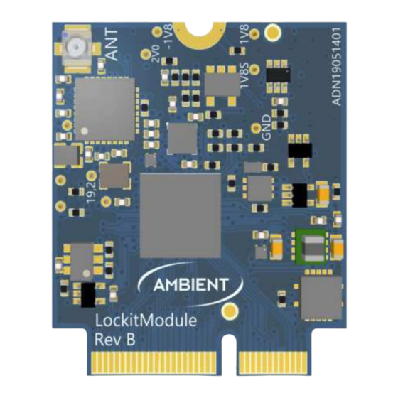
2.2.8 ACN RF Connector “ANT” carries the ACN IEEE802.15.4 RF signal via a standard U.FL socket. If RF output is not disabled permanently with no option of alteration through the user this connection must be properly terminated with a compliant 50 Ohms IPEX lead and suited antenna with max 2dBi in the according range. -
Page 6: Board Edge Connector Pinout
3 Board Edge Connector Pinout Signal Type Type Signal Ground Ground SWCLK * Int. LED_Red SWDIO * Int. LED_Green TRACESWO * Int. TC_In N_Reset * Int. Reserved N_StandBy * Int. Wordclock USB Data+ TC_Out_1 (buffered) USB Data- UART2_RX (RCP) USB VBUS UART2_TX (RCP) UART1_RX (ACN) Reserved... -
Page 7: Power
3.1 Power The module requires only one single power supply voltage with 3.3 V. An optional extra input (VBAT) can be used to supply the internal RTC of the microcontroller Name Type Description 1, 3 Power input, 3.3V DC stabilized, rated 250mA min. 2, 4, 74 Ground Signal and power ground Regulated DC output. -
Page 8: Communication Interfaces
Exemplary implementation of pull-up resistor 3.4 Communication Interfaces 2 physical host interfaces, UART and USB HID, are available to control and inquire status of the module. The API documentation is available as separate document. UART Name Type Description UART_RX 3.3V TTL, 5V tolerant UART_TX 3.3V TTL The serial 3V TTL UART1 interface is the most preferable interface for low level connection. -
Page 9: Leds
3.5 LEDs Name Type Description LED Red Status indicator, 3.3V, active low LED Green Status indicator, 3.3V, active low LED Blue Status indicator, 3.3V, active low RGB LED outputs allow to visualize the status of generator and ACN activity. It is strongly recommended to connect LEDs for debugging and optimum user experience. -
Page 10: Buttons
3.6 Buttons Name Type Description Button Green Momentary input Button Red Momentary input Button Pwr Momentary input Exemplary implementation using momentary switches 3.7 Timecode Name Type Description LTC In 1.8 – 5V Wordclock 3.3V TTL LTC Out Buffered output, variable from mic level to 3.3V TTL max. LTC Out 2 1.8V TTL Timecode is available on 2 pins of the module. -
Page 11: Sync
LTC_OUT2 on pin 39 is a direct connection to the processor and optimized for direct internal connection. When made available for external access we recommend a current limiting in line resistor, DC decoupling and tie to GND for defined DC state. Exemplary circuit for external use of LTC_OUT2 3.8 Sync Name... -
Page 12: Analog Inputs
Type Description UART4 TX Transmitter output ,1.8 V logic UART4 RX Receiver input ,1.8 V logic, 5V tolerant Pipelines a serial signal from UART or USB host control. Please contact Ambient for more information. Name Type Description UART5 TX Transmitter output ,1.8 V logic UART5 RX Receiver input ,1.8 V logic, 5V tolerant... -
Page 13: Spi Lines
4 Regulatory Requirements 4.1 EU (ETSI) The Ambient LockitModule ACN-LM is conform for use in European Union countries. If the module is incorporated into a product, the manufacturer must ensure the compliance of the final product to the European harmonized EMC and low-voltage/safety standards. A Declaration of Conformity must be issued for each of these standards and kept on file as described in Annex II of the R&TTE Directive. -
Page 14: Canada (Ic)
(1) This device may not cause harmful interference, and (2) this device must accept any interference received, including interference that may cause undesired operation FCC §15.105 (b): Note: This equipment has been tested and found to comply with the limits for a Class B digital device, pursuant to part 15 of the FCC Rules. -
Page 15: Japan
If additional filing is required please contact the person at Ambient Recording GmbH responsible for certification of the RF module. RF exposure statement (mobile and fixed devices) The instruction manual of the host shall include the following statement: This device complies with the RF exposure requirements for mobile and fixed devices. - Page 16 This device complies with the RF exposure SAR test exclusion requirements for portable devices, if a minimum separation distance of 15mm is kept. However, the device shall be used in such a manner that the potential for human contact during normal operation is minimized LockitModule Version 0.9 (18.10.2021) Page 16 of 17...
-
Page 17: Contact Information, Support
5 Contact Information, Support Ambient Recording GmbH Schleissheimer Str. 181c 80797 Munich, Germany Phone: +49 (0) 89 360 55 100 E-Mail: info@ambient.de Web: ambient.de Further documentation, firmware updates, and more: ambient.de/downloads/ LockitModule Version 0.9 (18.10.2021) Page 17 of 17...
Need help?
Do you have a question about the LockitModule ACN-LM and is the answer not in the manual?
Questions and answers