
Related Manuals for AUDAC LCR700

Summary of Contents for AUDAC LCR700
- Page 1 LCR700 LCR Meter AUDAC PROFESSIONAL AUDIO EQUIPMENT LCR Meter LCR700 User Manual & Installation Guide...
- Page 2 A U D A C P R O F E S S I O N A L A U D I O E Q U I P M E N T User Manual & Installation Guide AUDAC http://www.audac.be info@audac.be...
-
Page 3: Table Of Contents
Index INTRODUCTION ............................................. 3 ENVIRONMENT ............................................4 SAFETY REQUIREMENTS ........................................5 GENERAL INFORMATION ......................................... 6 OVERVIEW PANEL ..........................................7 SPECIFICATIONS ..........................................8 CAPITANCE ............................................8 INDUCTANCE ..........................................10 IMPEDANCE ............................................ 12 GETTING STARTED ..........................................13 1. AUTO POWER-DOWN ........................................ 13 2. -
Page 4: Introduction
1.000 Hz. This allows a measurement of great accuracy. The LCR700 has an Auto-Power OFF function, which helps conserve the lifespan of the battery, and a fuse detection function to inform that a fuse is open or damaged. The use of a DC adapter can also serve to disable... -
Page 5: Environment
Chapter Environment Do not place the unit in environments which contain high levels of dust, heat, moisture or vibration. Do not use the unit near water or other liquids. Make sure no water or other liquids can be spilled, dripped or splashed on the unit. This unit is developed for indoor use only. -
Page 6: Safety Requirements
Safety Requirements (Read the safety requirements before using the meter) Warning: Before taking any measurements, please isolate the DUT from the power supply. You should remove the test leads from the meter before replacing the batteries in order to avoid an electric shock. -
Page 7: General Information
Chapter General information Display L\C\R-4 ½ digits, max. reading of 19999. Q\D\R-4 digits, max.. reading of 9999 (Auto range) Measurement parameters Ls + (Q, D, Rs), Lp + (Q, D, Rp). Cs + (Q, D, Rs), Cp + (Q, D, Rp). Basic accuracy 0.5% for Impedance 0.7% for Inductance, Capacitance... -
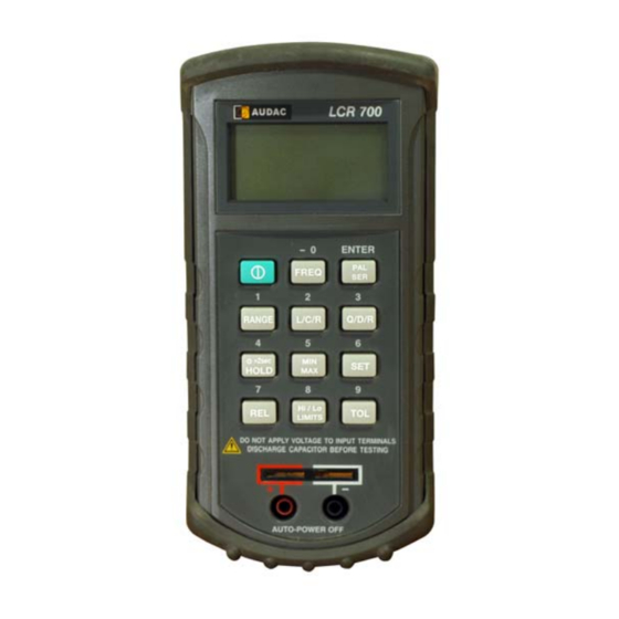
Page 8: Overview Panel
Overview panel Auto power off Parallel or Series Resistance RS232 Communication indicator indicator Recording mode indicator Tolerance indicator (percentage) Maximum reading indicator 1 KHz Frequency indicator Minimum reading indicator 120 Hz Frequency indicator Average reading indicator L, C or R function indicator AUTO Autoranging indicator ... -
Page 9: Specifications
Chapter Specifications CAPACITANCE: Test Frequency 120 Hz Range Min. Max. Note 20mF 1µF 10.000mF +/- (5.0%rdg + +/- (10%rdg + After short cal. 5counts) 100/Cx + 5counts) DF<0.1 DF< 0.1 2000µF 100nF 1999.9µ +/- (1.0%rdg + 5 +/- (2.0%rdg + After short cal. - Page 10 Test Frequency 1 KHz Range Min. Max. Note 2000µF 100nF 1000.0µF +/- (5.0%rdg + 5counts) +/- (10%rdg + 100/Cx + 5 After short DF<0.1 counts) DF<0.1 cal. 200µF 10nF 199.99µF +/- (2.0%rdg + 100/Cx After short +/- (1.0%rdg+ 3counts) +5counts) DF<0.5 cal.
-
Page 11: Inductance
INDUCTANCE: Test Frequency 120Hz Range Min. Max. Lx (DF<0.5) DF (DF<0.5) Note 20000H 10000H Not specified Not specified 2000H 100mH 1999.9H +/- (1.0%rdg + Lx/10000 +/- (2.0%rdg + 100/Lx After open +5counts) +5counts) cal. 200H 10mH 199.99H +/- (0.7%rdg + Lx/10000 + +/- (1.2%rdg + 100/Lx 5counts) +5counts) -
Page 12: Impedance
Test Frequency 1KHz Range Min. Max. Lx (DF<0.5) DF (DF<0.5) Note 2000H 100mH 1000.0H Not specified Not specified 200H 10mH 199.99H +/- (1.0% rdg + +/- (1.2%rdg + 100/Lx After Lx/10000+5counts) + 5counts) open cal. 19.999H +/- (0.7% rdg + +/- (1.2%rdg + 100/Lx Lx/10000+5counts) + 5counts) - Page 13 Remarks 1. Q value is the reciprocal of DF The specification is based on the testing sockets (clips) performed on the meter. L(C) x indicates the readings of inductance (capacitance) on the display. E.g. inductance (capacitance) = 18.888 H (F) then L(C) x=18888.
-
Page 14: Getting Started
Chapter Getting started 1. Auto Power-down If unused for about 10 minutes, the meter will power-down automatically. Press the button to resume the power-on mode. When the power is down, press the button to turn on the meter. The meter will return to its last operation before the power was turned off. -
Page 15: L/R/C Function Button (Only Main Display)
5. L/C/R Function Button (only Main display) The L/C/R key switches the measurement parameters in sequence L – C – R – L …. This is indicated on the LCD. When the meter is turned on, it is set to the measurement parameter that was used last before the meter was turned off. -
Page 16: Set
9. SET 1. The “SET” function can only be activated if no other function is active. 2. Press “SET” to enter the SET mode, and change to manual range mode automatically. 3. While in the SET function, the main display is cleared, the second display shows “SET” indicators. The LCD shows the following flashing indicators: ,TOL,and. -
Page 17: Rel Relative Mode (Only Main Display)
7. REL setting: Press the “RANGE” button to select the desired range. Press the “SET” button to enter the set mode and then the “REL” button. The “” symbol and the left digit of the 4 ½ digits will now flash for setting a reference value. -
Page 18: Maintenance
Maintenance Warning: Remove test leads before replacing battery or fuses. Battery replacement Power is supplied by a 9 volt “transistor” battery. (NEDA 1604, IEC 6 F22. The indicator appears on the LCD display when replacement is needed. Remove the two screws on the back of the meter and lift off the battery case. -
Page 19: Additional Information Rs-232 Command Table
Chapter Additional information RS-232 Command Table Use IR as the interface of Data transmission and use an external computer to start RS-232 functions. RS-232 Interface Parameters: Baud rate: 1200 Parity check: EVEN Data buts: 7 Stop bits: 1 (1) Setup Selections a. - Page 20 [U+/-19999]: REL SET setting value [V+/-19999]: Limits Hi setting value [W+/-19999]: Limits Lo setting value [X+/-19999]: TOL SET setting value [Y+/-19999]: TOL SET Hi setting value [Z+/-19999]: TOL SET Lo setting value d. Command [BXXXXXX]: Exit the SETUP mode (2) Read Data Command N: Read Meter current data and status.
- Page 21 value) / _(normal) R(REL) / S(REL SET) / _(normal) L(LIMITS) / _(normal) T(TOL) / S(TOL SET) / _(normal) B(Backlight) / _(normal) A(Adapter insert) / _(normal) B(Low Battery) / _normal CR (ASCII : 0DH) nl (LF) (ASCII: 0AH) (3) RS-232 Output Chart for Main Display Range 1KHz/120Hz 1 KHz 120 Hz...
- Page 22 (4) RS-232 Output Chart for Second Display Range (Rs=100Ω) (Rs=1KΩ, 10KΩ) (Rs=100KΩ) 999.9 99.99Ω 99.99Ω 99.99 999.9Ω 999.9Ω 999.9Ω 9.999 9.999KΩ 9.999KΩ 9.999KΩ 9999 99.99KΩ 99.99KΩ 99.99KΩ 999.9KΩ 999.9KΩ (5) FORMULA Rp = Rs (1+Q²) Cp= Cs [1/(1+D²) Cs= Cp (1+D²) Lp = Ls [1+(1/Q²)] Ls = Lp [Q²/(1+Q²)]...
-
Page 23: Personal Notes
Personal notes...
Need help?
Do you have a question about the LCR700 and is the answer not in the manual?
Questions and answers