
Subscribe to Our Youtube Channel
Summary of Contents for FOAMICO B 540-27 F
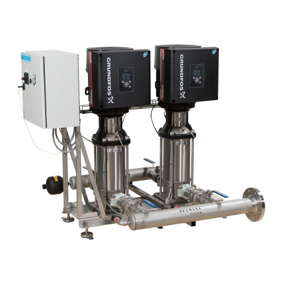
- Page 1 Manual FOAMICO Booster Station B 540-27 F + Feed pump (7009077) 1 B 540-27-F + feed pump_7009077 US – 07-02-2019...
-
Page 2: Table Of Contents
Ball valves. Non-return valves Suction filter / chemical hose. Technical Data Resulting outlet pressure. Spare parts Booster B 540-27 F – Feed pump Wiring diagram Flow Diagram Name Plate Declaration of Conformity 2 B 540-27-F + feed pump_7009077 US – 07-02-2019... -
Page 3: Introduction
1 Introduction FOAMICO congratulates you with your new Booster system. The B 540-27 is developed to connect to FOAMICO Cleaning Satellites. The Booster series are developed to be used for professional cleaning purpose. The system is manufactured mainly of high grad stainless steel. It is designed to meet today’s high hygiene standards. -
Page 4: Protection Against Frost
Should the manual get lost, please don’t hesitate to require another one from your agent 1.5 Declaration of conformity We FOAMICO declare that this product is in conformity with the following directives: - Machinery (2006/42/EC). - Electromagnetic compatibility (2004/108/EC). -
Page 5: Safety
CAUTION A dangerous situation Possible consequences: light or minor injuries. Can also be used in warn against damage to porperty or other goods. Prevention NOTICE A potentially damaging situation Possible consequences: the product or something in its vicinity could be damaged. - Page 6 WARNING Risk of poisoning / risk of allergic reactions Improper use of detergents can be dangerous, it can produce poisonous gas, severe chemical burns an allergic reactions. Do not connect or use detergent before having read the instructions from the Detergent supplier.
- Page 7 CAUTION Risk of injury When the low-pressure gun/nozzle is opened, the water jet will cause a certain back pressure. Make sure to have a strong grip on the handle and a firm foothold. WARNING Risk of ear damage The noise level from the equipment is less than 70dB (A). During rinsing, the operator is exposed to a higher noise level and can lead to loss of hearing.
-
Page 8: Precautionary Measures
Rinsing with water, spreading foam and sanitizer within the stated boundaries. Any other kind of application or use beyond this is considered to be inappropriate and deviant concerning the requirements, and may lead to dangerous situations. FOAMICO is not liable for any sequential damages brought about by this. -
Page 9: Transport
Work in the connection with installations, start up, and maintenance on the Foamico cleaning systems should only be done by authorized electricians, because the valid national regulations concerning prevention of working accidents. E.g. high voltage regulations: EN 60204-1 (IEC 204-1), VBG4 DIN- VDE 0100/0113/0160 or other local regulations) must be respected. -
Page 10: Location And Mounting
Damage to equipment caused by blockage Any wastewater entering the machine may severely damage the equipment. At the supply pipe to the main station a valve and filter must be installed. We recommend using Original FOAMICO installations set. CAUTION Damage to equipment caused by blockage Any wastewater entering the machine may severely damage the equipment. -
Page 11: Electrical Supply
The water should be connected to the inlet shown in POS A. fig. 4.1 CAUTION Property damage If the pump runs dry it may be damaged. The pump must be filled with water and vented. Open the vent valve POS. D fig. -
Page 12: Operation
CAUTION The connection has to be done to a main switch installed next to the station. Always consult the pump manual before making the connections Supply voltage and mains: 3 x 380-480 V. -10%/ + 10 %, 50/60 Hz, PE. NOTICE The voltage and frequency is marked on the main station’s and the pumps nameplates. -
Page 13: Stop Procedure
4.2 Stop procedure 1. The booster is stopped by turning the switch POS C fig. 4.1 into “0”. NOTICE When the system is not used it is recommended to Turn the switch POS C fig. 4.1 into “0” NOTICE In case of service the Electrical main switch shall always be turn off. STOP: Turn the On/Off switch POS. - Page 14 Figure 4.2 Display photo pump stopped • Operating mode: Stop. Pump is stopped • Resulting setpoint. Setpoint = inlet pressure + maximum pump pressure. (maximum setpoint 27 bar) • Inlet pressure: Actual measured inlet pressure. • Liquid temp.: water temperature in top of the pump. Figure 4.3 Display photo Pump running •...
-
Page 15: Troubleshooting
5 Troubleshooting ATTENTION! When the system is service, the main power switch POS. F Fig. 4.1 must be turned off! Fault Cause Action No rinsing pressure. Booster or main station not started. Start booster/or main station. Too many users on the same time. Check maximum number of users. -
Page 16: The Pump Does Not Start
5.2 The pump does not start The pump does not start even though there is flow through the pump. Do the following: Reset the unit. Turn the Switch POS. C fig 4.1 into “0” position for 5 seconds. Turn the Switch POS. C fig 4.1 into rinse position “I”. -
Page 17: Other Faults
- High water temperature Limit 2 exceeded: is the supply water below 70°C/158°F?? Limit 2 exceed: The water temperature at the top of the pump has been higher than 80°C/176°F for more than 3 seconds. Check the temperature setting for the water supply. Maximum water temperature is 70°C/158°F?. -ATTENTION: Before it is possible to reset the system it must cool down to below 80°C/176°F. -
Page 18: Maintenance
Check the nozzles on a regular basis. 1 to 2 times every month is recommended. Change the nozzle if they are damaged. To be sure you will get the optimized result we recommend using FOAMICO nozzles. 6.3 Low pressure valves / guns They must be checked regular. -
Page 19: Ball Valves
NOTICE Non- return valves should be checked once every week. It is recommended to change every 1-2 year. Use only Original FOAMICO non-return valves. Use only Original Foamico non-return valves. 6.7 Suction filter / chemical hose. The suction filter for chemical should be clean once every week. It is recommended to change filter and chemical inlet hose every year. -
Page 20: Technical Data
7 Technical Data B 540-27 F – Feed pump Water: Unit Max. water consumption l/min. Max. Temperature °C 3” Pipe dimension inlet inch 3” Pipe dimension outlet inch Power Supply: Standard voltage 380-500 50/60 Max power consumption 54,8 A – 43,3A... -
Page 21: Spare Parts
8 Spare parts 8.1 Booster B 540-27 F – Feed pump *** All Measurements are average US – 07-02-2019 B 540-27-F + feed pump_7009077... - Page 22 Figure 8.1 Booster US – 07-02-2019 B 540-27-F + feed pump_7009077...
-
Page 23: Wiring Diagram
Table 8.1 Booster station B540-27-F – Feed pump 9 Wiring diagram The electrical diagram is delivered as a separate part of the manuals US – 07-02-2019 B 540-27-F + feed pump_7009077... -
Page 24: Flow Diagram
9.1 Flow Diagram In and outlets A. Water inlet A. Water inlet Components 2. Ball valve 2. Ball valve 4. Pump 4. Pump 7. Pressure transmitter 7. Pressure transmitter US – 07-02-2019 B 540-27-F + feed pump_7009077... -
Page 25: Name Plate
10 Name Plate 1. Company Name 8. Maximum pressure 2. Production date 9. Min/Max inlet pressure. 3. Serial number 10 Power 4. Item Number 11. Current 5. Model type 12. Voltage 6. Maximum allowed flow 13. Frequency 7. Maximum temperature in Celsius US –... -
Page 26: Declaration Of Conformity
11 Declaration of Conformity Declaration of Conformity We FOAMICO declare under our sole responsibility that the MO NEXT 0127-0 - 5, MO NEXT 0227-0 - 5, MO NEXT 0145-1 – 5. MS NEXT 0115-1 – 5, MS NEXT 0127-1 – 5, MS NEXT 0227-1 – 5 MS NEXT 0327-1 - 5, MS NEXT 0427-1 –...
Need help?
Do you have a question about the B 540-27 F and is the answer not in the manual?
Questions and answers