Page 1
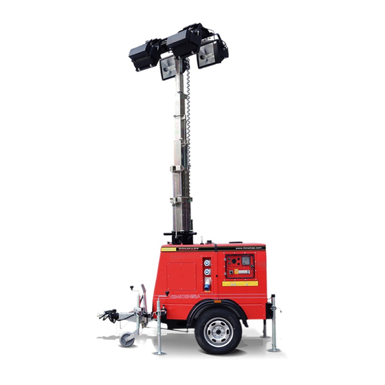
OPERATING AND MAINTENANCE MANUAL LIGHTING TOWER | COMPACT SERIES STANDARD HEAVY DUTY...
Page 2
CONTENTS 1. Introduction 2. Safety regulations 3. Generic description 4. Commissioning 5. Operations to be performed once the activity has been completed 6. Maintenance 7. Trouble shooting 8. Hydraulic diagram 9. Wiring diagram 10. Warranty conditions | PAGE 2...
Page 3
Only in this way can we ensure an optimal service under totally reliable and secure conditions. HIMOINSA, S.L. considers that it should note in all honesty that the information described in this manual is valid on the date on which such information is issued, given that aspects such as technological advances and updates of current regulations oblige us to make modifications without prior notice.
2. SAFETY REGULATIONS Before using this equipment read carefully the indicated safety regulations and find out about the local safety requirements. The installation, operation, maintenance and repairs shall be carried out only by authorized and competent staff. The owner is responsible for the maintenance of the lighting tower in conditions of security.
Page 5
STOP immediately • Fill the fuel tank to a maximum 90% of its total capacity. Make sure and contact with the Technical Department at HIMOINSA. that the cap of the tank is perfectly closed.
Page 6
Agency of your country to check the necessary licenses for your particular unit. Picture Location Information • Check that the hitch and coupling on the towing vehicle are rated Located on the connections equal to, or greater than the trailer’s “gross vehicle weight rating” They warn of the danger in case an alien from the alternator to the object collides with the timing belts or...
Page 7
Picture Location Information Located on the control panel. They warn of electric shock hazard. Always located on the ther- They indicate the prohibition of manipulat- mal-magnetic switch. ing the genset when the switch is on. SAFETY REGULATIONS | PAG. 7...
Page 8
3. GENERIC DESCRIPTION 3.1 COMPONENTS OF THE LIGHTING TOWER HIMOINSA lighting towers have been made with top quality materials, and with the effort of our technical and production team, without sparing resources to achieve high-performance and versatile operation lighting towers. They are composed of a tower kit and a gen-set, all in a compact and well-balanced trailer.
Page 9
Diesel Diesel Diesel • Transportation kit, the tower is ready for road transport. Including Tank capacity as standard: jockey wheel, straight drawbar with ball coupling and Filling of the tank External External External connections for signalling lights (brake lights, indicators), as well as Running time position and handbrake reflectors.
Page 10
Standard CONTROL PANEL Control and protection M7 manual control unit M7 manual control unit M7 manual control unit unit 2425 mm (Standard and Eco) 2457 mm (Heavy Duty) Thermal-magnetic circuit breaker to protect the Standard Standard Standard spotlights and the auxilia-...
Page 11
3.3 PACKING PLAN 13.5 mt 9 units per trailer 20’ 40’ 4 units per container 9 units per container Fig. 5 Apolo Eco UNIDADES POR CONTENEDOR Fig. 4 Fig. 6 Apolo Compact Standard Apolo Heavy Duty GENERIC DESCRIPTION | PAG. 11...
Page 12
4. COMMISSIONING Before starting the lighting tower check its correct location on a firm and totally levelled ground, to ensure a proper operation and stability in case of a strong wind. NOTE Do not raise the mast if strong winds (more than 80km/h) or thunderstorms are expected in the area.
Page 13
• Turn the jack handle clockwise to start levelling the trailer until it is in firm contact with the ground and the trailer is as level as possible. Fig. 4 Fig. 5 4.3 ADJUSTMENT OF THE SPOTLIGHTS Fig. 2 • Only the legs are removed from the front, the rear legs are fixed and Before raising the tower it may be necessary to adjust the lamps.
4.4 RAISING THE TOWER The trailer must be levelled with the outriggers extended before raising the tower mast and must remain extended while the tower is up. Failure to level the trailer or extend the outriggers will severely reduce the stability of the unit and could allow PULL PULL the tower to tip and fall.
Page 15
NAME: SIGNATURE OLD CODE: DESCRIPATION: Manual start NEW CODE: DESIGN: 1/17/2014 REVISED/ Nº P.: 1/17/2014 Miguel Utrillas APPROVED: CTRA.MURCIA-SAN JAVIER KM 23.600 C.P. 30730 - MURCIA - ESPAÑA CODE: REVISION: Free voltage contact start www.himoinsa.com Fig.13 COMMISSIONING | PAGE 15...
Page 16
The spotlights must be always switched off when raising/lowing or aiming. DATE: OLD CODE: DESCRIPATION: NAME: SIGNATURE NEW CODE: 1/17/2014 DESIGN: REVISED/ Nº P.: 1/17/2014 Miguel Utrillas APPROVED: CTRA.MURCIA-SAN JAVIER KM 23.600 C.P. 30730 - MURCIA - ESPAÑA CODE: REVISION: SCALE: www.himoinsa.com Telf. 968 191 128 COMMISSIONING | PAGE 16...
Page 17
APPROVED: CTRA.MURCIA-SAN JAVIER KM 23.600 C.P. 30730 - MURCIA - ESPAÑA to the slight vibrations that inevitably occur when the mast is being lowered. www.himoinsa.com • Press the down button installed on the control panel Fig.2 OPERATIONS TO BE PERFORMED ONCE THE ACTIVITY HAS BEEN COMPLETED | PAGE 17...
5.3 RETRACT TELESCOPIC LEGS 5.4 ROAD TRAVEL Wind the jockey wheel up for road travel. IMPORTANT To proceed with the retraction of the telescopic legs make sure that the jockey NOTE wheel is lowered and fixed to the surface. Fig. 3 & 4. Make sure when raising the jockey wheel that fits perfectly, this will avoid turns during the transport which could cause damage to the machine.
6. MAINTENANCE 6.1 GENSET MAINTENANCE General maintenance (refer to the gen-set manual) 6.2 LIGHTING TOWER One might well say that thanks to the simple nature of the system and to the quality of the materials used during the manufacturing process, the tower itself does not actually require exhaustive maintenance.
Page 20
8. Steel cables and pulley sets: Lamp specifications: • Carry out periodic checks of the cables state, every 100 hours or • Name: single ended halide once a month. • Base Designation: MOG(E39) • When the steel cable decreases by 10% of the rated diameter due to •...
8. HYDRAULIC DIAGRAM 6.3 MOBILE EQUIPMENT Maintenance of mobile equipment (ref. Manual of head, inertia coupling and shaft of the mobile kit) 7. TROUBLE SHOOTING Cylinder Due to the simplicity of the system, breakdowns are practically none. However, in the event of any failure, please contact with our after-sales service. Valve Tube Pressure relay...
The coverage of this warranty is ONLY applicable to the end user of the equipment recognized by Himoinsa. In the case of generator sets, it is only applicable to those generator sets that operate together with a manual or automated control panel manufactured and/or installed by HIMOINSA.
All replaced parts have to be returned to Himoinsa and will become of its property. • In case of defects in the engine or the alternator, HIMOINSA informs 10.3 USER RESPONSIBILITIES that the assistance covered by the warranty will be provided by the...
Page 47
• Any cost that may exceed the purchasing price of the product. HIMOINSA informs the user that he or she is obliged to follow the Maintenance and Use Manual and to keep it together with the rest of the technical •...
Page 48
Fax: +34 968 19 12 17 | Fax - Exports: +34 968 33 43 03 www.himoinsa.com Himoinsa reserves the right to change any feature without prior notice. The illustrations may include optional equipment and/or accessories. Not contractual images. The technical indications described in this manual correspond to the information available at the moment of printing.
Need help?
Do you have a question about the STANDARD and is the answer not in the manual?
Questions and answers