
Summary of Contents for Neutronics 1100
- Page 1 MODEL 1100 MODEL 1100 Oxygen Analyzer / Controller Percent Range High Purity Instruments OPERATIONS MANUAL Manual: MN-A-0004 P/N: C5-06-4900-01-0 Rev: Date: August 16, 2013 ECO: 9760...
-
Page 3: Table Of Contents
Operations Manual Model 1100 Table of Contents FOR YOUR SAFETY: ............................III WELCOME ............................... IV CHAPTER 1 – INTRODUCTION AND OVERVIEW ..................1 .............................. 1 ENERAL ............................1 EATURES ......................3 YSTEM ARDWARE VERVIEW 1.3.1 Main Board ..........................3 1.3.2 Relay Board .......................... - Page 4 G – MSDS M ............... 51 PPENDIX ATERIAL AFETY HEETS H – W ........................54 PPENDIX ARRANTY INTENDED USE FOR THE MODEL 1100 ...................... 54 Page ii Manual Part Number: Manual File Name: Manual Revision Level: E C5-06-4900-01-0 MN-A-0004 ECO: 9760...
-
Page 5: For Your Safety
Always remove the freshness seal from the MAX-250 sensor before using. • Always assure the pressure of gas entering the model 1100 is 1-3 psig (not to exceed 15" Hg • vacuum or 7 psig). Always calibrate the model 1100 at an equivalent pressure and flow rate to the measured gas. -
Page 6: Welcome
Copyright ©2013 Neutronics Inc. This work is protected under Title 17 of the US Code and is the sole property of Neutronics Inc. No part of this document may be copied or otherwise reproduced, or stored in any electronic information retrieval system, except as specifically permitted under US copyright law, without the prior written consent of Neutronics Inc. -
Page 7: Chapter 1 - Introduction And Overview
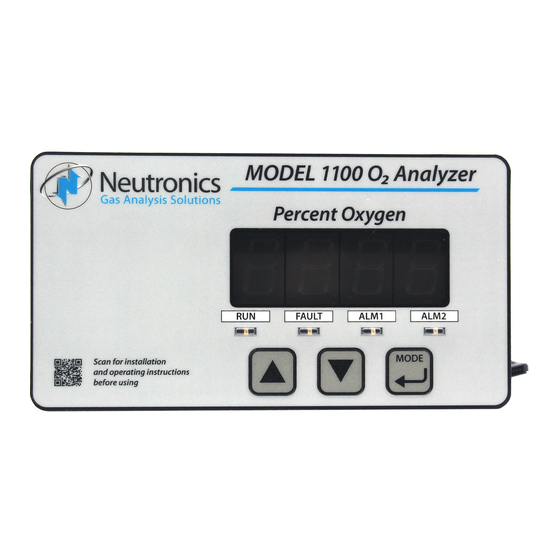
The Compact Series analyzers are designed to be flush mounted to a panel or console. Because of the small size of the Model 1100 analyzer, it can be integrated into a variety of equipment or control panels. The Remote Sensor Module can be mounted close to the sampling point to assure the fastest response possible. - Page 8 O N L Y . Plug-‐in S tyle S ensor Removeable T erminal B locks Connection Rear Views Figure 1 – Model 1100 oxygen analyzer Page 2 Manual Part Number: Manual File Name: Manual Revision Level: E...
-
Page 9: System Hardware Overview
1.3.2 Relay Board The Relay Board houses relay contacts for all of the Alarm and Control features of the 1100. The relays are mapped discretely to each alarm to provide electrical outputs for reporting, and process control use. -
Page 10: Control Panel
There are #8-32 threaded mounting studs at each of the four corners for flush mounting of the model 1100 to a stationary control or equipment panel. The gasketed panel is suitable for NEMA type 4/IP20 environments when properly installed. -
Page 11: Sensor Flow-Through Head
It is also an important component of the electrostatic discharge (ESD) shielding design. Since the model 1100 is a flush mounted system, the portion of the instrument housed in the chassis will be located behind the control panel or embedded within the customer equipment enclosure. - Page 12 Model 1100 Operations Manual 4-‐ 20 m A O utput RS -‐ 232 C OM L ine Analog V oltage O utput Range I D O utput Fault R elay O utputs Alarm ...
-
Page 13: Analyzer Inputs And Outputs
1.4.1 The Oxygen Sensor Input The oxygen sensor electrical input to the model 1100 is used to indicate the oxygen concentration measured by the model MAX-250 oxygen sensor. It is proportional to the oxygen present in the measured gas at the sensor membrane. The oxygen sensor input is a female 3-pin 180° DIN connector designed to mate with the supplied sensor interface cable connector. -
Page 14: Analog Current Output
Analog voltage and Analog current outputs when auto-ranging is used. It provides an indication of the Analog outputs’ selected full-scale. There are five range ID voltage levels used in the 1100 to correspond with its five output ranges (Appendix E – range / output chart). -
Page 15: The "Mode" Pushbutton
1.5.3 The “MODE” Pushbutton The “MODE” pushbutton on the control panel can be used to program the model 1100. This momentary push-button soft key is used to navigate the operational modes available through the control panel. Its function is menu-driven. -
Page 16: Chapter 2 - System Installation And Start-Up
Model 1100 Operations Manual 2 – S HAPTER YSTEM NSTALLATION AND TART Installing the Analyzer S TE P 1: L OCATE THE ANAL YZE R... PANE L C UTOUT S TE P 2: INS TAL L THE S E NS OR…... -
Page 17: Step 1 - Locate And Mount The Analyzer Unit
Step 1 – Locate and Mount the Analyzer unit The model 1100 is designed to be mounted flush to the surface of a stationary equipment control panel. Select a suitable location for the analyzer unit where the digital display and status LED’s will be easy to read, and the interface buttons on the display panel will be easy to access. -
Page 18: Step 2 - Install The Remote Sensor
2.1.2 Step 2 – Install the Remote Sensor The model 1100 is supplied with a model MAX-250 oxygen sensor, and sensor flow-through head for connection to a sampled process gas stream, and a sensor interface cable with a rubberized sheath to protect the sensor and the sensor electrical connector from dust and liquid spray. - Page 19 Operations Manual Model 1100 Figure 8b – GP Sensor and flow-through head mounting 2.1.2.2 Sample Inlet Port Pneumatic connection to the measured process for sample extraction is made at either of the two interchangeable 1/8" FNPT fitting around the side of the flow-through head. For connecting the flow-through head to the measured process, use 1/8"...
-
Page 20: Step 3 - Install The Analyzer
Model 1100 Oxygen analyzer. DANGER: The model 1100 analyzer is not rated intrinsically safe or explosion proof. Be certain that no flammable gases are present in the area where the Model 1100 analyzer will be installed. CAUTION: The model 1100 housing is not rated waterproof. - Page 21 Operations Manual Model 1100 A label depicting the terminal block arrangement is affixed to the top of the chassis for easy reference during installation and maintenance (VAC and Wall Mount configuration shown below). The terminal blocks feature screwed terminals. The terminal blocks are also removable for ease of wiring or removal of the analyzer module.
- Page 22 Model 1100 Operations Manual VDC P OWER I NPUT, VDC+ 18-‐ 30 V DC -‐ or -‐ VAC P OWER I NPUT, AC-‐ L AC-‐ N 90-‐ 264 V AC, 4 7-‐ 63 H z ...
- Page 23 Attach the sensor interface cable to the model 1100 analyzer female 180° 3-pin DIN cable connector. For the wall mount version (analyzer mounted in an enclosure) of the analyzer, connections to the sensor are made at terminal block TB4.
- Page 24 TB3 on the rear of the analyzer chassis. The Analog current output is a negative ground, non-isolated 0-20mA, or 4-20 mA current loop. 12 VDC Power is supplied by the model 1100 analyzer. Maximum electrical loading is 250 Ohms. Be certain to match the terminal pins against the terminal ID label on the top of the analyzer chassis.
- Page 25 Operations Manual Model 1100 2.1.3.9 RS-232 Service Port For interfacing with any standard PC computer via serial port, use 20-AWG, 3-conductor, shielded, stranded-wire, jacketed cable, terminated on one end with a female DB9 connector. The shielding should be drained to dc ground at the computer.
-
Page 26: Starting Up And Commissioning The System
S E T AL ARM 1 & 2 Figure 11 – Start-up outline The Model 1100 is shipped ready to use, right from the carton. Factory default configuration settings are listed in Appendix C. Those settings will be suitable for most applications. Review the factory default configuration settings before commissioning your system. -
Page 27: Step 2 - Calibrate The Unit
Refer to Appendices E and F for all valid range and output settings available on the model 1100. If any changes are necessary, they can be performed via the control panel (section 4.1.1) or the service port (section 4.1.2). -
Page 28: Chapter 3 - Analyzer Operation
“MODE” key. When a user mode is accessed via the control panel, the model 1100 aborts any system mode active, and holds the state of Alarm-1, Alarm-2, Fault, and Heater OK relay outputs until the user returns the unit to Run mode. - Page 29 Certified standard grade bottled gas at 20.9% oxygen concentration • WARNING Do not calibrate the model 1100 using zero gas. If the unit is calibrated on zero gas, it will not operate properly. 3.2.1.2 Step-2: Remove the Oxygen Sensor from On-line Service The oxygen sensor requires removal from on-line service prior to calibration.
-
Page 30: Set/View Alarm-1 Mode
3.2.1.5 Step-5: Return the Oxygen Sensor to On-line Service When the calibration procedures are completed, the model 1100 is ready to return to service. Disconnect the calibration gas from the oxygen sensor by completely removing the installed 1/8" FNPT fitting from the sensor flow-through head sample inlet port. If a calibration manifold has not been installed, reconnect the sample inlet port to the process for in-service oxygen measurement (section 2.1.2.2). -
Page 31: Return To Run Mode
Run mode, and the “RUN” indicator LED stays lit. Indicator LED’s mapped to aborted modes go out. When the model 1100 analyzer detects valid user-input, it enters into one of the user modes accordingly – Calibration, Set/View Alarm-1, Set/View Alarm-2, View Active Faults, or User Setup. -
Page 32: Alarm-1 Active Mode
3.3.5 FAULT ACTIVE Mode The model 1100 initiates Fault Active mode when it has detected that one or more Fault criterion have been satisfied (section 4.3.1). The “FAULT” indicator LED will light and the Fault relay will change state. The Fault status will be cleared automatically when no Fault criterion have been satisfied. -
Page 33: Chapter 4 - Maintenance And Troubleshooting
All configuration parameters may be changed by the user via the Service Port. Important: Before changing any of the model 1100 settings, refer to Appendix C – Factory Setup for reference. If the user has any questions before proceeding with changing analyzer settings, please contact the Neutronics Service Department for assistance. - Page 34 User Setup mode 5 allows the user to adjust the high and low span values of the Analog 4-20mA output from the model 1100. To access user setup mode 5, use the “MODE” key to scroll through the user setup mode menu as normal, until user setup mode 5 is reached. The LED display will show “4.00”...
- Page 35 4.1.1.10 User Setup 8: Factory Setup Restore. This parameter allows the user to return the model 1100 to its initial factory-commissioned settings. Always perform a gas calibration after restoring factory settings. Valid Settings: 88. A setting of 88 will activate the Factory Setup restore.
-
Page 36: System Setup Via Service Port
RS-232 Service Port Interfacing with HyperTerminal in Microsoft Windows 95 or later Turn off your PC computer, and remove power from the Model 1100. Complete the instructions for wiring and connecting the Model 1100 to a PC computer (section 2.1.3.10). Apply power to the Model 1100, and start up the PC computer. - Page 37 If the typed letters DO show on the monitor screen and serial communications with the model 1100 still has not been established, then PC COM port pins 2 & 3 (1100 pins 9 & 10) may be reversed. Verify the cable wiring (section 2.1.3.10). If no transmitted data from the model 1100 is seen on the monitor screen, call the Neutronics Inc.
- Page 38 The order of data in each packet is as follows: Start Transmit • O Concentration • Fault codes active • List of Fault Codes • Alarm-1 status • Alarm-1 status • End Transmit. For detailed information on data formats, please contact the Neutronics Service Department. Page 32...
- Page 39 Column headings from left to right: Time since last re-boot • Mode • O2 Concentration • Alarm-1 status • Alarm-2 status • list of Fault codes active. For detailed information on data formats, please contact the Neutronics Service Department.
- Page 40 4.1.2.9 System Information Display The System Information Display U10 is a list of all the current settings for the 1100 analyzer. It is accessed from the Setup Main Menu by typing “1” or “I” on the RS-232 Terminal. Page 34...
- Page 41 The RS-232 Alarm/Relay Setup menu U20 provides access to all of the settings related to the Alarms, controls, and relays on the Model 1100 analyzer. It is accessed from the Setup Main Menu by typing “2” or “R” on the RS-232 Terminal. To navigate backwards, use the <Esc> or “Q”...
- Page 42 4.1.2.10.7 Fault Relay Active during Warm-up This setting determines the active status of the Fault relay during the Model 1100 warm-up routine (section 4.3.1.2). The activate setting may be set to “YES” or “NO”. This setting is accessed from the Alarm Relay Setup Menu by typing “7” or “W” on the RS-232 terminal.
- Page 43 Operations Manual Model 1100 4.1.2.11 (U30) Analog Output Setup Menu The RS-232 Analog Output Setup menu U30 provides access to all of the settings related to the Analog Voltage Output (TB3-Pin 5, TB3-Pin 6) and Analog Current Output (TB3-Pin 7, TB3-Pin 8).
- Page 44 The RS-232 Display/Auto-Range Setup menu U14 provides access for the user to map the display and Analog output range scale(s) of the Model 1100 to suit the application (Appendix E – Range / Analog output Chart). The Analog Output Range may be set to 1 (fixed range 0-1 %) • 2 (fixed range 0-10 %) •...
- Page 45 4.1.2.16.1 Calibration Mode Auto Return to RUN This setting determines the minimum time that the Model 1100 allows after exiting from control panel or service port user menus, before returning the unit to on-line status. The calibration mode auto return setting is accessed from the Control panel Locks menu by typing ”T” on the RS-232 terminal.
-
Page 46: Change Factory Settings Via Hardware Jumpers
4.1.3.1.1 Remove the unit from service Make certain that all interfacing to the model 1100 is disabled at the user device. Make sure that interrupting outputs, from the unit will not interfere with normal process monitoring or control. Disconnect power from the model 1100 unit. Disconnect the removable terminal blocks from the rear of the model 1100 chassis. - Page 47 Operations Manual Model 1100 JP4 / JP5 JUMPERS SELECT VOLTAGE OUTPUT RANGE (1=SHORTED; 0=OPEN) = 0-1 VDC = 0-5 VDC = 0-10 VDC Figure 17 – Range select jumper settings Page 41 Manual Part Number: Manual File Name: Manual Revision Level: E...
-
Page 48: Routine Periodic Maintenance
Model 1100 does not require any major periodic servicing. Calibration of the sensor on a known gas source should be performed on a regular basis. The chart below should serve as a general guide for maintenance personnel. -
Page 49: Troubleshooting
Fault Code 8 – A concentration reading is not yet available The “concentration reading is not yet available” fault is active when the model 1100 is not ready for online service. It is active during start-up, calibration and during fault code-2 – relays are in standby mode. - Page 50 Fault Code 15 – Bad user calibration The “bad user calibration” fault indicates that the user has attempted to calibrate the model 1100 with what appears to be a faulty sensor. Possible causes of fault code 15 are: Incorrect or contaminated calibration gases, improper calibration procedure, faulty sensor.
-
Page 51: Chapter 5 - Appendices
Operations Manual Model 1100 5 – A HAPTER PPENDICES Appendix A – Spare Parts List PART NUMBER DESCRIPTION Operations Manual 5-06-4900-01-0 *Replacement Oxygen Sensor – GP type (mA output signal) 8-01-1000-02-2 *Replacement Oxygen Sensor – GP type (mV output signal) 8-01-1000-02-3 *Replacement Oxygen Sensor –... -
Page 52: Appendixb - Specifications
Model 1100 Operations Manual Appendix B – Specifications OXYGEN SENSOR External weak-acid galvanic oxygen fuel-cell DISPLAY 0.75" 7-segment LED digital display, 4 characters Displays oxygen from 0 to 100 percent. Resolution: 0.00–0.99 % X.XX 1.00–9.99 % X.XX 10.0–99.9 % XX.X 100.0 %... - Page 53 Operations Manual Model 1100 RANGE 0–1 % • 0–10 %• 0–25 % • 0–50 % • 0–100 % ±2.0 % of range @ calibrated temperature and pressure ACCURACY RESPONSE TIME < 20 seconds WARM UP TIME None HUMIDITY Analyzer: 0-95 % non-condensing...
-
Page 54: Appendixc - Analyzer Factory Configuration Settings
Model 1100 Operations Manual Appendix C – Analyzer Factory Configuration Settings Alarm and Relay Setup Information NON-FAILSAFE Alarm-1/Alarm-2 Relays Failsafe/Non-Failsafe ASCENDING Alarm-1/Alarm-2 Relay Ascending/Descending Alarm-1 Trigger Level 10 % Alarm-2 Trigger Level Display Range Analog Voltage Output 0–1 % Fixed 0–1 VDC... -
Page 55: Appendixd - Control Panel Hot -Key Functions
Model 1100 Appendix D – Control Panel Hot-Key Functions For convenience in operating and troubleshooting, the Model 1100 has four control panel hot-key functions that can be performed quickly via the control panel without entering the normal control panel, or service port user menus. -
Page 56: Appendixe - Range / Output
Model 1100 Operations Manual Appendix E – Range / Output RANGE NAME MEASURED DISPLAY ANALOG RANGE ID RANGE RANGE VOLTAGE OUTPUT FULL AUTO 0.00 % – .9 % X.XX 0–1 % 5.63 VDC RANGE 1.00 % – 9.99 % X.XX 0–10 %... -
Page 57: Appendixg - Msds Material Safety Data Sheets
Model 1100 Appendix G – MSDS Material Safety Data Sheets 1. Product Identification Oxygen sensor, galvanic type, model MAX-250 furnished by Neutronics Inc. • 456 Creamery Way • Exton, PA USA, 19341 • Telephone: 610-524-8800. 2. Hazardous Ingredients of Solution Electrolyte composed of weak acid solution (Acetic Acid) Lead Acetate, Trihydrate. - Page 58 Model 1100 Operations Manual 6. Health Hazard Data Lead (use for Lead Acetate & Lead): TLV/TWA 0.15 mg/m3, PEL 0.05 mg/m3 Toxicity: Intraperitoneal Rate LD 50 for lead acetate trihydrate is 200 mg/Kg Carcinogenicity: This substance is listed as a NTP anticipated human carcinogen and an IARC animal carcinogen.
- Page 59 Neutronics with respect to the data, the product described, or their use for any specific purpose, even if that purpose is known to Neutronics.
-
Page 60: Appendixh - Warranty
The original purchaser's sole and exclusive remedy, unless varied by written agreement with NEUTRONICS, INC., is that NEUTRONICS, INC. will, at NEUTRONICS, INC.'s option, repair or replace any defective part which is returned to NEUTRONICS, INC. within ninety (90) days of discovery of the defect.
Need help?
Do you have a question about the 1100 and is the answer not in the manual?
Questions and answers