Advertisement
Quick Links
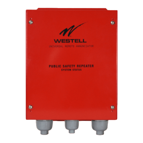
CS19-URA-003
Universal Remote Annunicator
Installation and User Guide
This installation and user guide provides instructions to ensure correct and safe installation and interconnection of the Westell
CS19-URA-003 Universal Remote Annunicator (URA).
Westell's CS19-URA-003 URA can operate with any
manufacturer's public safety bi-directional amplifier (BDA)
and battery backup system. The URA connects to BDA relay
outputs to provide visual and audible annunciation at 1 or 2
locations up to 3000 feet away.
The CS19-URA-003 includes:
•
a NEMA4 / UL 508A Interface Unit (IU) that mounts next to
the BDA
•
One or two Remote Annunciators
URA Installation Overview
Figure 1 below depicts a typical URA installation.
BDA Closet
Westell eBDA or any
PS BDA with relay outputs
The URA Interface Unit is usually co-located with the Public
Safety BBA and its BBU. Multi-conductor cables connect the
relays inside the URA Interface Unit to the BDA's relay outputs
and the Fire Alarm Control Panel. CAT5 or CAT6 Ethernet cable
links the URA interface unit to one or two Remote Annunciators
located up to 3000 feet away.
Installation Steps
1. Gather tools and materials.
Tools:
•
Drill and drill bits
•
Wrenches
URA
Interface
Unit
Product
label
Figure 1. Overview of CS19-URA-003 Universal Remote Annunicator installation
•
Level
•
Screwdrivers
•
Wire stripper
•
Pliers
•
Knife to cut flexible rubber conduit
Materials:
•
Flexible rubber conduit
•
CAT5 or CAT6 cable for Remote Annunciator connection(s)
•
Standard wall-mounted 2-gang electrical junction box (1 for
each Remote Annunciator)
Fire Control Room
Fire Alarm Panel
Remote
Annunciator
2. Mount URA Interface Unit
The URA Interface Unit is wall-mounted using the brackets at
top and bottom of the back of the unit. Follow these steps:
A. Determine the mounting location. Consider:
• proximity to the BDA and/or BBC cabinets
• clearances needed to open cabinet(s) and install conduits
B. Lift the Interface Unit to the mounting location and
mark each mounting hole. Use a level to ensure level
mounting. Remove conduit fittings as needed to access
lower mounting holes.
C. Drill holes at each mark for wall anchors fitting #8 or
Lobby
2nd Remote
Annunciator
Cat 5/6 cable
Multi-conductor cable
W E S TELL .CO M
Advertisement

Summary of Contents for Westell CS19-URA-003
- Page 1 CS19-URA-003 Universal Remote Annunicator Installation and User Guide This installation and user guide provides instructions to ensure correct and safe installation and interconnection of the Westell CS19-URA-003 Universal Remote Annunicator (URA). Westell’s CS19-URA-003 URA can operate with any • Level manufacturer’s public safety bi-directional amplifier (BDA)
- Page 2 CS19-URA-003 Installation and User Guide Installation Steps Front view with cover removed Unit Status LEDs Remote Annunciator COMM FAILURE MUTE POWER Ports RA-2, RA-1 Output Terminals Mute button AC FAIL BATT ACTIVE BATT CAPACITY LOW Input Terminals BATT CHARGE FAIL...
- Page 3 CS19-URA-003 Installation and User Guide Remote Annunciator Operation 5. Connect Remote Annunciator Cables When the power feed is on, the POWER LED at the top of the URA interface unit circuit board will glow green and the AC Connect a CAT5 or CAT6 cable long enough to reach the...
- Page 4 , and Optima Management System EdgeLink™ are trademarks of Westell, Inc. All other names are trademarks of their respective owners. Information is correct at time of printing and is subject to change without notice. Westell, Inc. is an Equal Opportunity/Affirmative Action employer.
Need help?
Do you have a question about the CS19-URA-003 and is the answer not in the manual?
Questions and answers