Table of Contents
Advertisement
Quick Links
Manual
Installation, Startup and Applications
Web-Thermometer
valid for models:
#57725 Web-Thermometer 1x Pt100/Pt1000
#57707 Web-Thermometer 2x Pt100/Pt1000
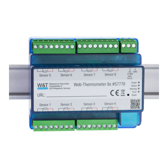
#57778 Web-Thermometer 8x Pt100/Pt1000
#57714
Web-Thermometer NTC
#57715
Web-Thermometer Pt100/Pt1000
#57726 Web-Thermometer Relay
#57720 Web-Thermo-Hygrometer
#57729 Web-Thermo-Hygrometer ++
#57713
Web-Thermo-Hygrobarometer
Release 1.52 09/2021
Advertisement
Table of Contents


Need help?
Do you have a question about the 57725 and is the answer not in the manual?
Questions and answers