Sign In
Upload
Download
Table of Contents
Contents
Add to my manuals
Delete from my manuals
Share
URL of this page:
HTML Link:
Bookmark this page
Add
Manual will be automatically added to "My Manuals"
Print this page
×
Bookmark added
×
Added to my manuals
Manuals
Brands
Genie Manuals
Mobility Aid
GL-10
Operator's manual
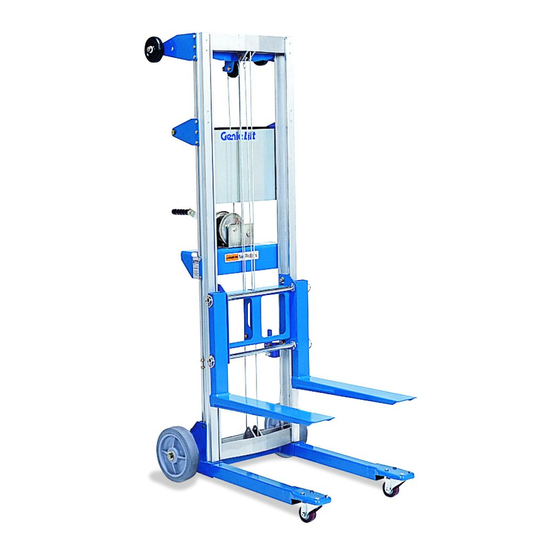
Genie GL-10 Operator's Manual
Genie lift operator's manual model gl-4 gl-8 gl-10 gl-12
Hide thumbs
1
Table Of Contents
2
3
4
5
6
7
8
9
10
11
12
13
14
15
16
17
18
19
20
21
22
23
24
25
26
page
of
26
Go
/
26
Contents
Table of Contents
Bookmarks
Advertisement
Table of Contents
1
Table of Contents
2
Safety
3
Legend
4
Pre-Operation Inspection
5
Function Tests
6
Workplace Inspection
7
Operating Instructions
8
Battery & Charger Operating Instructions
9
Transport Instructions
10
Load Capacity Charts
11
Decals
12
Specifications
Download this manual
Operator's Manual
First Edition
Sixth Printing
Part No. 35566
Table of
Contents
Previous
Page
Next
Page
1
2
3
4
5
Advertisement
Table of Contents
Need help?
Do you have a question about the GL-10 and is the answer not in the manual?
Ask a question
Questions and answers
Related Manuals for Genie GL-10
Mobility Aid Genie GL-12 Operator's Manual
Genie lift operator's manual model gl-4 gl-8 gl-10 gl-12 (26 pages)
Mobility Aid Genie GL-4 Operator's Manual
Genie lift operator's manual model gl-4 gl-8 gl-10 gl-12 (26 pages)
Mobility Aid Genie GL-8 Operator's Manual
Genie lift operator's manual model gl-4 gl-8 gl-10 gl-12 (26 pages)
This manual is also suitable for:
Gl-12
Gl-4
Gl-8
Table of Contents
Save PDF
Print
Rename the bookmark
Delete bookmark?
Delete from my manuals?
Login
Sign In
OR
Sign in with Facebook
Sign in with Google
Upload manual
Upload from disk
Upload from URL


Need help?
Do you have a question about the GL-10 and is the answer not in the manual?
Questions and answers