Advertisement
Quick Links
Specifi cations
Setpoint Range
AGL1 Series: 5-100mA Field Adjustable
AGL2 Series: 80-950mA Field Adjustable
AGL3 Series:
Tri-Set, 5, 10 & 30 mA,
Jumper Select
Voltage Range
Up to 1,500 VAC (Monitored Circuit)
Frequency Range
50-400Hz (Monitored Circuit)
Output Description: Electromechanical relay
1.0A @ 120 VAC, 2A @ 30 VDC
Status (Red) LED = Relay has operated
Response Time
200 ms @ 5% over setpoint.
60 ms @ 50% over setpoint.
15 ms @ 500% over setpoint
Power Supply
120 VAC Operates from 66-132 VAC
(50-400hz)
Optional Power
24 VAC or 24 VDC Operates from
19.2-28.8 Volts)
Power (Green) LED=Power supply
energized
Power Consumption
2.5 Watts
Dimensions
4.25"H x 3.0"W x 3.25"D,
(108x76x83mm), aperture 1.82" (46mm)
dia.
Case
UL 94V-O Flammability Rated
Environmental
5 to 158 DegF (-15 to 70 DegC), 0-95%
RH, Non Condensing
Terminal torque
5.3 inch-pounds
Power Supply Notes
All low-current Ground-Fault Sensors are sensitive devices
that require reasonable care in system design to avoid false
trips caused by high electrical noise levels. Keep in mind
that the best way to reduce noise in a system is to suppress
it at its source.
1. Keep the sensor power isolated from noisy circuits.
2. Do not power the sensor with the same circuit that switches
contactors or other high current, inductive loads.
System Grounding
Good design practice and code require that all AC power
systems be grounded. AGL Series sensors are designed to
work on grounded AC power systems. They may not operate
properly on ungrounded systems.
Model Number Key
AGL1 - NOR1 - 120 - LA - 005-N
Options
None (Blank)
N
Setpoint
005 to 950
TR3
Options
LA Normally De-energized
Power Supply
24U 24 VAC/DC
120 120 VAC
Output Type
NOR1
SPST (Normally open, closes on fault)
NCR1
SPST (Normally closed, opens on fault)
Setpoint Range
1 5-100mA, Adjustable
2 80-950mA, Adjustable
3 Tri-Set, 5, 10 & 30 mA, Jumper Select
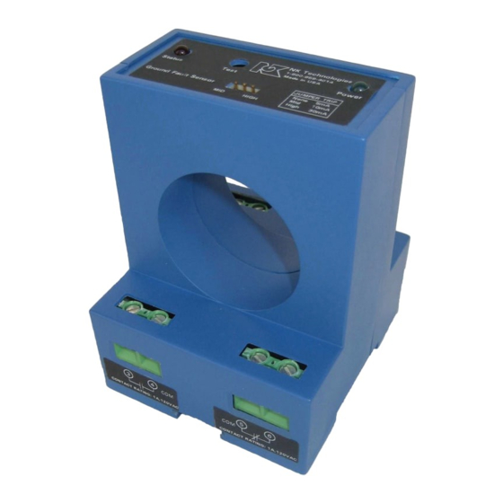
AGL Series Ground Fault Sensor
Know Your Power
Know Your Power
Other NK Technologies Products Include:
AC & DC Current Transducers
AC & DC Current Operated Switches
1φ & 3φPower Transducers
Current & Potential Transformers (CTs&PTs)
3511 Charter Park Drive, San Jose, CA 95136Toll free:
800-959-4014, Phone: 408-871-7510
Fax: 408-871-7515
sales@nktechnologies.com, www.nktechnologies.com
Electical Noise Immun.
INSTRUCTIONS
Factory Adjusted
Setpoint in mA (specify
when ordering)
Tri-Set, 5, 10 & 30 mA,
Jumper Select
AGL1, 2 & 3 SERIES
with Latching Relay Outputs
Quick "How To" Guide
1. Run all current carrying conductors through
sensor window
A. Use an auxiliary CT if conductors do not fi t. Consult
Factory for CT selection.
2. Mount the sensor to a surface if needed.
3. Connect output & power wiring.
A. Use up to 14 AWG copper wires.
B. Make sure power and load matches those shown on
the senors' label.
4. Test
A. Pressing the "TEST" button tests the sensors internal
circuits. CAUTION: The output and any connected
loads will switch!
Ground Fault Sensors
AGL SeriesLatching. 3.0 06/10, P/N 49-068-0004
Advertisement

Related Manuals for NK TECHNOLOGIES AGL1 Series


Summary of Contents for NK TECHNOLOGIES AGL1 Series
- Page 1 Specifi cations Model Number Key Setpoint Range AGL1 Series: 5-100mA Field Adjustable AGL1 - NOR1 - 120 - LA - 005-N AGL2 Series: 80-950mA Field Adjustable Options AGL3 Series: Tri-Set, 5, 10 & 30 mA, None (Blank) Jumper Select Electical Noise Immun.
- Page 2 Description Installation & Wiring AGL Series sensors work in the same environment as mo- AGL Series sensors monitor all current carrying wires in Momentary Reset tors, contactors, heaters, pull-boxes, and other electrical single or three phase systems to detect ground faults. They The sensor will not work properly if the reset terminals are enclosures.