Advertisement
Quick Links
Specifi cations
Power Supply
24 VAC/DC (19-24V)
120 VAC (90-130V)
Power Consumption 2.4 VA max. (24V power)
3 VA max. (120V Power)
Trip point Range
30, 50 & 100 mA, Switch Select
Voltage Range
Up to 600 VAC (Monitored Circuit)
Frequency Range
12-398Hz (Monitored Circuit)
Relay Output
SPDT 1A@120 VAC, 2A@30 VDC
Frequency of Monitored Circuit
<17 Hz
17-32 Hz
>32 Hz
Time Delay
0-10 seconds plus response time
Isolation Voltage
1240 VAC, tested to 5KV
Sensor Power Indication Green LED = Power untripped
Output Tripped Status
Red LED = Output tripped
Dimensions
2.91"Hx3.86"Wx1.45"D
(73.9x98.0x36.8 mm)
Aperture 0.75" (19.1 mm) inside diameter
Case
UL 94V-0 Flammability Rated
Environmental
-4 to 122°F (-20 to 50°C)
Power Supply Notes
All low-current Ground-Fault Sensors are sensitive devices
that require reasonable care in system design to avoid false
trips caused by high electrical noise levels. Keep in mind
that the best way to reduce noise in a system is to suppress
it at its source.
1. Keep the sensor power isolated from noisy circuits.
2. Do not power the sensor with the same circuit that switches
contactors or other high current, inductive loads.
System Grounding
Good design practice and code require that all AC power
systems be grounded. AGV Series sensors are designed to
work on grounded AC power systems. They will not operate
properly on ungrounded systems.
Model Number Key
AGV 3 - SDT - 24U - LA - TR3
Response Time
<140 ms
<75 ms
<45 ms
Output Type
SDT - Single Pole, Double Throw
Setpoint Range
3 - Tri-Set, 30, 50, & 100 mA, Slide Switch
Select
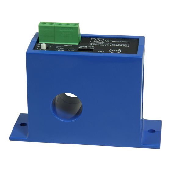
AGV Series Ground Fault
Know Your Power
Know Your Power
Other NK Technologies Products Include:
AC & DC Current Transducers
AC & DC Current Operated Switches
1 & 3Power Transducers
Current & Potential Transformers (CTs&PTs)
3511 Charter Park Drive, San Jose, CA 95136
Phone: 800-959-4014 or 408-871-7510
Fax: 408-871-7515
sales@nktechnologies.com, www.nktechnologies.com
Setpoint
TR3 - Tri-Set, 30/50/100 mA
Switch Select
Output
DEN - Normally De-energized
ENE - Normally Energized
LA - Latching
Power Supply
24U - 24 VAC/DC
120 - 120 VAC
(Form C SPDT Relay)
INSTRUCTIONS
AGV Series
Ground Fault Sensors
For VFD Driven Loads
Quick "How To" Guide
1
. Pass all current carrying conductors include neutral
return not ground return through sensor window.
2. Mount the sensor to a surface if needed.
3. Connect output & power wiring to unit.
A. Use 22-14 AWG copper wires rated for 75°C mini-
mum.
B. Make sure power and load matches those shown on
the senors' label.
C. Set the desired trip point using the slide switch to
choose 30, 50, or 100 mA setting.
4. Energize the monitored circuit. Add delay before
the output changes state as required by turning pot
clockwise, arrow pointing to the seconds added.
5. Test
A. Pressing the "TEST" button tests the sensor's
internal circuits. CAUTION: The output and any
connected loads will switch! The LED shows red
when a fault is detected or test button is pressed.
B. For latching output models (-LA), momentarily
shorting between the "reset" terminals will release
the latched output contact. Do not apply voltage to
the reset terminals.
490061007 Rev 1
Advertisement

Related Manuals for NK TECHNOLOGIES AGV Series


Summary of Contents for NK TECHNOLOGIES AGV Series
- Page 1 Good design practice and code require that all AC power 3511 Charter Park Drive, San Jose, CA 95136 the latched output contact. Do not apply voltage to systems be grounded. AGV Series sensors are designed to Phone: 800-959-4014 or 408-871-7510 the reset terminals.
- Page 2 Installation & Wiring Connect a momentary dry contact to the reset terminals AGV Series sensors work in the same environment as mo- AGV Series sensors monitor all current carrying wires in (6&7). Limit wire run to 200’ of 18 AWG or larger wire.
- Page 3 Typical Installations Trouble Shooting The AGV series ground fault detector was purposely 1. During motor start, there may be an exces- designed to allow the protection of a load driven with sive amount of current loss due to capacitance a variable frequency drive to sense a fault to earth low leakage.
Need help?
Do you have a question about the AGV Series and is the answer not in the manual?
Questions and answers