
Summary of Contents for FLEET Gen 2 Portal FSPOR0201-2
- Page 1 Fleet Gen 2 Portal User Manual Title of Document MAN-PTL-002 Revision 0.5 | 27/07/21 - DRAFT Role Name Position Prepared By : Oscar Whalley Mechanical Engineer Approved By : Kody Cook Lead Systems Engineer...
-
Page 2: Table Of Contents
MAN-PTL-002 v0.4 ONTENTS Contents Introduction Hardware Tech Specs Variants Installation Wiring up Your Portal 2.1.1 12V DC Power Jack 2.1.2 Serial Port 2.1.3 Ethernet Port 2.1.4 Satellite Port 1 2.1.5 Satellite Port 2 2.1.6 WiFi Antenna Port 2.1.7 LTE Antenna Port 2.1.8 GPS Antenna Port 2.1.9... -
Page 3: Satellite Port
MAN-PTL-002 v0.4 3.3.5 LoRaWAN Device Classes Operation Adding LoRa Devices Distributing your LoRaWAN Network Accessing your Data Troubleshooting FCC Notices... -
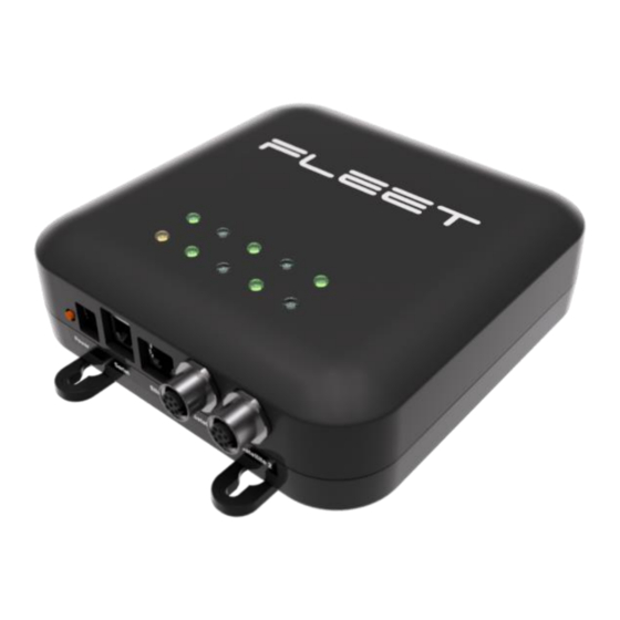
Page 4: Introduction
MAN-PTL-002 v0.4 NTRODUCTION 1.1 Hardware The following is a complete list of the hardware required to set up the Fleet Portal. 12V DC Wall Adapter Ethernet Cable WiFi/LTE/GPS antenna Fleet Gen 2 Portal Fleet Gen 1 Satellite Modem Orbcomm Satellite modem LoRa Antenna NOTE: Depending on the version of your Portal, you may not require a satellite modem for operation. -
Page 5: Installation
Power Input 5.5mm x 2.1mm DC Barrel Jack SERIAL Serial RJ11 RS232 Ethernet RJ45 SAT1 Satellite Modem 1 8-pin M12 Circular connector Fleet Modem SAT2 Satellite Modem 2 8-pin M12 Circular connector Orbcomm Modem WIFI WiFi LTE/NB-IoT LORA2 LoRa 2 LORA1... -
Page 6: Dc Power Jack
The Portal comes with 2 Satellite Ports, both of which use an 8-pin M12 Circular connector. Satellite Port 1 should be used with the Fleet Modem included. This can be achieved by connecting the Fleet Modem to Satellite Port 1 using the included cable by inserting the cable end into the 8-pin M12 Circular connector and then hand-tightening it. -
Page 7: Wifi Antenna Port
MAN-PTL-002 v0.4 2.1.6 WiFi Antenna Port The included WiFi Antenna Port uses an SMA female connector which should be connected to the WIFI/LTE/GPS Antenna. This can be done by using the cable with a green end marked “WIFI” coming out of the Antenna into the WiFi Port. The male SMA connector on the end of the cable should be inserted and then hand-tightened. -
Page 8: Mechanical Mounting And Assembly
MAN-PTL-002 v0.4 2.2 Mechanical Mounting and Assembly 2.2.1 Portal Mounts Diagram 2.2.2 Mounting your Portal Your portal can be mounted in a number of different ways based on the specifications ordered: ● Standard wall mount feet can be utilised which use #8 Pan Head Screw. ●... -
Page 9: Mounting Your Antenna
And if solar panels are being utilised, then an MPPT is recommended which can be attached to the Serial Port using an RJ11 male connector. Note: The Fleet Modem also utilises M4 screws and so the same kind of mounting methods mentioned above for the Portal can also be used with the Fleet Modem. -
Page 10: Configuration
MAN-PTL-002 v0.4 ● 2 x LoRa ● WiFi ● GPS ● LTE Where possible, it is recommended to use a low profile multiband antenna for WiFi, GPS and LTE. This are omnidirectional and should be mounted as high as possible. The LoRa antenna/s are typically selected based on the application. -
Page 11: Method 2: Wired Ethernet - Direct Connection
MAN-PTL-002 v0.4 The Portal is now connected. The Portal can be accessed with the following IP address: 192.168.4.1 3.1.2 Method 2: Wired Ethernet – Direct Connection The Portal can also be accessed using the Ethernet port. This is a less portable method of connecting to the Portal, however, Wi-Fi can still be used on your device while you operate the Portal. -
Page 12: Method 3: Wired Ethernet - Local Network
MAN-PTL-002 v0.4 3.1.3 Method 3: Wired Ethernet – Local Network The Portal can also be assigned an IP address by connection to a router. This is useful if you require remote access to the Portal that cannot be serviced via Wi-Fi or direct Ethernet connection. 1. -
Page 13: Portal Configuration
MAN-PTL-002 v0.4 3.3 Portal Configuration 3.3.1 Device Groups Device Groups are objects that separate the use cases of your LoRa network. For instance, one device group may be soil monitoring and another might be water reservoir monitoring. Device groups provide a way for the user to group common sensors together to make managing them easier. Each device group contains scripts which are called codecs. -
Page 14: Creating Custom Codecs
As mentioned above, one may change the codecs within an application for custom use. It is not recommended to change encoding codecs without consulting Fleet first, as unsuitable changes made here could make it impossible to retrieve your data after satellite backhaul. -
Page 15: Region Selection / Frequency Bands
The Portal supports a variety of devices. More devices are constantly being added, and each of these require a different codec. If you need to use a device which is not presently supported, contact Fleet and we can provide support in creating your own codec. -
Page 16: Lorawan Device Classes
MAN-PTL-002 v0.4 3.3.5 LoRaWAN Device Classes LoRaWAN comes in three different device classes: A, B & C. The Portal supports all three classes of device. The device group created on the portal must match the classes supported by the device being used. Failure to do so will result in the device not being able to receive downlinks from the Portal. - Page 17 ● Application Session If the nodes were provided by Fleet, these details will be included in the packaging. If purchased independently, you will need to consult the user manual and data sheets of those nodes and sensors. To add a LoRa Device to an application: 1.
- Page 18 MAN-PTL-002 v0.4 5. Enter activation keys: a. OTAA devices: Enter activation keys in the appropriate boxes. Note: the exact fields shown here will depend on the LoRaMAC version of your device group b. ABP devices: Enter the device address and activation keys in the appropriate boxes. Note: the exact fields shown here will depend on the LoRaMAC version of your device group 6.
-
Page 19: Distributing Your Lorawan Network
If necessary, consider running an external antenna from inside the structure to the outside to boost signal range. 4.3 Accessing your Data Your data will be sent automatically over the backhaul network and will be available at https://nebula.fleet.space. ROUBLESHOOTING For assistance troubleshooting the portal please contact Fleet at support@fleet.space. -
Page 20: Fcc Notices
MAN-PTL-002 v0.4 FCC Notices This device complies with Part 15 of the FCC Rules and with Innovation, Science and Economic Development Canada’s licence-exempt RSS(s). Operation is subject to the following two conditions: (1) This device may not cause interference; and (2) This device must accept any interference, including interference that may cause undesired operation of the device.”...
Need help?
Do you have a question about the Gen 2 Portal FSPOR0201-2 and is the answer not in the manual?
Questions and answers