Table of Contents

Summary of Contents for SCIENTIFIC INSTRUMENTS 6290
- Page 1 HAND HELD PC USER INTERFACE MANUAL MODEL 6290 TANK GAUGING SYSTEM Record of Revisions RFEA # Description Rev by Date Appr by Date Initial Release 05/25/00 See RFEA 0569 10/24/00 SCIENTIFIC INSTRUMENTS, INC. 090-252...
-
Page 2: Table Of Contents
TABLE OF CONTENTS 1 INTRODUCTION ....................1-1 Connection ....................1-1 Operation....................... 1-1 2 CONTROL MODULE USER INTERFACE.............. 2-1 Continuous Display Mode................2-1 2.1.1 Explanation of Values on Screen ............. 2-1 2.1.2 Keys for Operation ................... 2-1 2.1.3 Simulator Mode ..................2-2 User Menus .................... - Page 3 2.2.2.4.2 Option 2, Data Collection (Edit Data Collection) ....2-8 2.2.2.4.2.1 Option 1, Profile Settings ..........2-8 2.2.2.4.2.2 Option 2, Top Scan Settings ........2-8 2.2.2.4.2.3 Option 3, Profile Start Control ........2-8 2.2.2.4.2.4 Option 4, Profile Fixed Time......... 2-9 2.2.2.4.3 Option 3, Time ..............
- Page 4 3.2.1.2 Option 2, Derived Units ..............3-2 3.2.1.3 Option 3, Voltages................ 3-2 3.2.1.4 Option 4, A/D Converter Menu ............. 3-2 3.2.1.5 Option 5, Cal Level Sensors ............3-3 3.2.1.6 Option 6, Serial Link Tests ............3-3 3.2.1.7 Option 9, Quit ................3-3 3.2.2 Edit SC Parameters .................
-
Page 5: Introduction
The Hand Held PC (HHPC) is the most basic user interface for the Scientific Instruments Model 6290 (M6290) level, temperature, and density gauge. There are several ways to operate the M6290 after installation, such as via Modbus and the PC- based User Interface Unit, but the only way to configure the system is with the HHPC. - Page 6 If it is necessary to perform maintenance functions such as changing system parameters, performing tests, or changing the mode of operation, the operator can press one of three menu buttons to bring up one of the three system menus. The resulting menus will be different for the Control Module and the Signal Conditioning Card.
-
Page 7: Control Module User Interface
Continuous Display Mode Figure 1 shows a typical display for the Continuous Display mode. The current values for temperature and density of the liquid are shown along with the current mode and probe position. System 6290 -159.45 ° C 445.48 kg/m Manual 20.002 m... -
Page 8: Simulator Mode
causes the probe to drive up slowly. If UP is pressed again, the probe will change to medium speed. If it is pressed one more time, it will switch to its fastest speed. Speed is indicated on the display by the number of vertical arrows. -
Page 9: Main Menu
Menu provides access to various system displays and maintenance functions. 2.2.1.1 Option 1, Regular Display This option gives the regular display for the 6290 and is the default display on power-up. This display shows the measure of temperature and density, along with probe position and other important system quantities. -
Page 10: Option 4, Serial Link Tests
The second option in the Maintenance Functions menu is "Force Host Exit." This should not be chosen because this will cause the host program to exit and the 6290 will no longer be operational; this step is only necessary when re-programming the host. If this option should be chosen by mistake, it will be necessary to remove and re-apply AC power to reset the host processor. -
Page 11: Option 2, Reference, Interlock
When option 1 is selected, the current values for these quantities will be shown. If it is not desired to change these values, simply press ESC to return to the menu. If it is necessary to change these quantities, press EDIT and you will be prompted to enter new values. -
Page 12: Option 4, Sensor Trip Points
prevents the probe from driving freely and reel alarm is not enabled to stop the system. 2.2.2.1.4 Option 4, Sensor Trip Points This option displays the trip points for the upper and lower level sensors, bottom reference, and upper level sensor shorted. In addition, the set points for the D/A converters are shown. -
Page 13: Option 2, Alarm Levels
2.2.2.3 Option 3, Density (Edit Density Parameters) Choosing option 3 on the Edit Parameters menu brings up the "Edit Density Parameters" submenu. 2.2.2.3.1 Option 1, Calibration Values This option gives access to the calibration values for the density meter. These include T0, D0, and K. Density is calculated according to the formula 2( D... -
Page 14: Option 2, Data Collection (Edit Data Collection)
The "Power Up Action" determines what the system will do on power up. If this parameter is set to a 1, the 6290 will perform a calibration on power up. If this parameter is set to a 0, the 6290 will remain in Manual Stop after power up. -
Page 15: Option 4, Profile Fixed Time
2.2.2.4.2.4 Option 4, Profile Fixed Time This option allows the user to start a profile at a certain hour each day. The user may set the hour and minute. Note that a profile will only be started at this time if the system is in Auto and Program Enable is set to a “2”, as described above. -
Page 16: Option 4, Configuration (Modbus Configuration)
M6280 Modbus specification. (Some changes are still necessary.) This option should only be used if the DCS software cannot be changed to match the new 6290 specification, since there are a number of advantages in using the new 6290 specification. 2.2.2.6 Option 6, Simulator Choosing option 6 on the Edit Parameters menu brings up the "Simulator... -
Page 17: Option 2, Temperature & Density
level sensor on and the upper level sensor off, the current position will immediately be taken as liquid level, since this is the condition for liquid level. The previous entered value will be immediately overwritten. 2.2.2.6.2 Option 2, Temperature & Density When inputting values for temperature and density, there are two approaches. -
Page 18: Operator Command Menu
the number of the profile to be recalled. After the profile is recalled, the number of the new profile in memory will be displayed. 2.2.3 Operator Command Menu Pressing "CMND" on the HHPC keypad brings up the Operator Command menu. The Operator Command menu allows the user to set the current system mode of operation. -
Page 19: Signal Conditioning Card User Interface
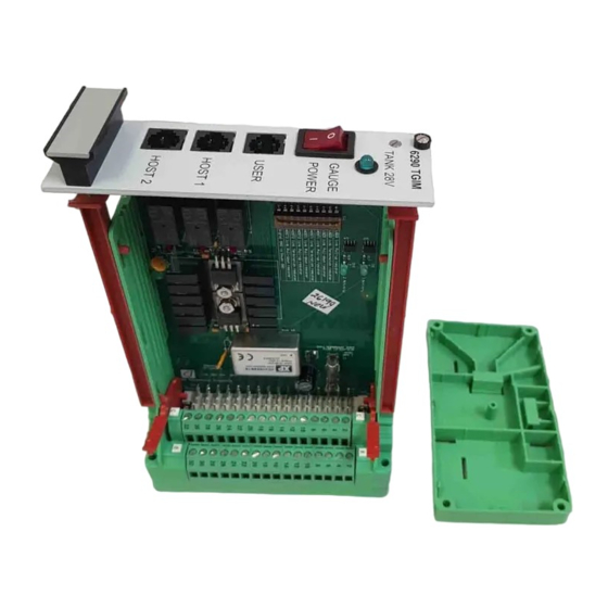
SIGNAL CONDITIONING CARD USER INTERFACE Plugging the HHPC into the Signal Conditioning Card allows the user access to some quantities and features that cannot be accessed by plugging in to the CPU Card (the RJ11 jack on the left of the Interconnect Card). The Signal Conditioning Card can only be accessed by plugging into the RJ11 jack on the right side of the Interconnect Card. -
Page 20: Signal Conditioning Card Menus
The upper level sensor cannot be checked for a short circuit, since this is how bottom reference is indicated. If the system indicates bottom reference falsely, it is possible that the upper level sensor is actually shorted. There are four keys that may be used to exit the continuous display mode. Pressing ESC (escape) is the same as pressing MAIN, which will bring up the Main Menu. - Page 21 3.2.1.5 Option 5, Cal Level Sensors This option causes an automatic calibration of the level sensors. This should be done with the probe in liquid near the bottom of the tank, but not at the bottom, since the bottom reference switch will short out the upper level sensor.
- Page 22 3.2.3 A/D Converter Menu The A/D Converter menu is accessed either from option 4 of the Main Menu or by pressing "CMND" in the continuous display mode. The A/D Converter menu is used to access all functions relating to calibration and diagnostics with the main A/D converter.
- Page 23 3.2.3.1.5 Option 5, Reset A/D Converter This option is available here for convenience. It should not need to be used under normal circumstances. 3.2.3.2 Option 2, Enable Auto-Range This option is used to put the converter back on auto range after using options 3 or 4.
Need help?
Do you have a question about the 6290 and is the answer not in the manual?
Questions and answers