
Summary of Contents for GETOtec MAGIC
- Page 1 Assembly Instructions MAGIC Distance Measuring System MAGIC Encoders MAGIC-PG GETOtec Schwindstraße 9 Telefon: +49 (0)89 954164-10 info@getotec.de D-80798 München Telefax: +49 (0)89 954164-11 www.getotec.de...
-
Page 2: Table Of Contents
4.1.1 Assembly of the magnetic and protective cover tape.............12 4.1.2 Assembly of the encoder......................13 Assembly of the HIWIN MAGIC-PG ....................13 4.2.1 Assembly of the profile rails ....................13 4.2.2 Assembly of the magnetic scale and the protective cover tape ..........13 4.2.3... - Page 3 HIWIN MAGIC dimensions .......................21 8.1.2 HIWIN MAGIC-PG dimensions....................22 Technical data of the MAGIC encoder....................23 Technical data of the magnetic scale ....................24 Reference switch..........................25 Spare parts and item numbers ..................26 ...
-
Page 4: Information About This Document
Troubleshooting and error elimination • Shutdown, disassembly and disposal Applicability of these assembly instructions These assembly instructions are applicable to HIWIN distance measuring systems with the following product designations: HIWIN MAGIC • • HIWIN MAGIC-PG Symbols used WARNING Warnings serve to protect people against concrete or possible dangers to life and health. -
Page 5: Safety
Proper use The HIWIN MAGIC is a magnetic distance measuring system for measuring tasks with linear movement within an automated system. It is used, above all, in linear motors. The distance measuring systems named may not be used outdoors or in hazardous areas where there is a risk of explosions. -
Page 6: Safety Information For Storage And Transportation
• The distance measuring sensor is operated at a low voltage, so there is not normally any risk of injuries or fatalities from this alone. HIWIN_Montageanleitung_MAGIC_V1.1_EN.doc - 10/2010 GETOtec GETOtec Schwindstraße 9 Schwindstraße 9 Telefon: +49 (0)89 954164-10 Telefon: +49 (0)89 954164-10 info@getotec.de... -
Page 7: Additional Information
Fax: +49 (0)781 / 9 32 78-90 If you have questions about the documentation, suggestions or corrections, please send a fax to the following fax number: +49 (0)781 / 9 32 78-90 GETOtec Schwindstraße 9 Telefon: +49 (0)89 954164-10 info@getotec.de D-80798 München... -
Page 8: Product Descriptions
Product descriptions The magnetic distance measuring systems of the HIWIN MAGIC series are optimized for measuring the distances traveled in linear movements and particularly on linear motor axes. They are particularly suitable for use in harsh environmental conditions and are resistant to oil, dirt, vibrations and shocks. -
Page 9: Connection
Figure 3.5 Cable with coupling (optional) Reference switch The MAGIC encoder delivers index signals at a distance of 1 mm. For the definition of a reference point, a reference switch ("cam switch") is required. For this purpose, HIWIN offers an inductive proximity switch (see figure 3.6). -
Page 10: Scope Of Delivery
Figure 3.6 Reference switch on mounting Scope of delivery Depending on customer requirements, the distance measuring systems MAGIC and MAGIC-PG are offered in different forms and with different scope. Individual components can be supplied to retrofit existing linear guideway systems. -
Page 11: Assembly
The numbers used for identification in the assembly instructions are also shown in the item overview in chapter 9 in order to make it easier to select individual parts. Assembly of the HIWIN MAGIC Figure 4.1 shows the assembly steps described below for the HIWIN MAGIC. Positive counting direction Figure 4.1 Assembly of the HIWIN MAGIC 4.1.1 Assembly of the magnetic and protective cover tape... -
Page 12: Assembly Of The Encoder
Make sure that the minimum cable bending radius of 40 mm is not underrun. Assembly of the HIWIN MAGIC-PG Figure 4.2 shows the assembly steps described below for the HIWIN MAGIC-PG. 4.2.1 Assembly of the profile rails Fit the profile rails as described in the assembly instructions for the linear guideways. - Page 13 Pull the block onto the rail again. Ensure no balls fall out while you are doing this. NOTE The bond strengthens under pressure. The final strength is obtained after approx. 48 hours at room temperature. HIWIN_Montageanleitung_MAGIC_V1.1_EN.doc - 10/2010 GETOtec Schwindstraße 9 Telefon: +49 (0)89 954164-10 info@getotec.de D-80798 München Telefax: +49 (0)89 954164-11 www.getotec.de...
-
Page 14: Assembly Of The Magic
4.2.3 Assembly of the MAGIC-PG encoder On the side where the MAGIC encoder [7] should be mounted, remove the metal scraper [6] by loosening the screws. Do not disassemble the deflection unit [9]! Screw the headless screw [8] into the threaded hole of the deflector. -
Page 15: Reference Switch
The distance measuring sensor is operated at a low voltage, so there is not normally any risk of injuries or fatalities from this alone. Do not operate the sensor with a voltage other than the one specified. This can destroy it. NOTE HIWIN_Montageanleitung_MAGIC_V1.1_EN.doc - 10/2010 GETOtec Schwindstraße 9 Telefon: +49 (0)89 954164-10 info@getotec.de D-80798 München Telefax: +49 (0)89 954164-11 www.getotec.de... -
Page 16: Cable And Connector
V2 – / B ¯ Purple Ref + / Z Ref – / Z ¯ Gray Connector housing Shielding HIWIN_Montageanleitung_MAGIC_V1.1_EN.doc - 10/2010 GETOtec GETOtec Schwindstraße 9 Schwindstraße 9 Telefon: +49 (0)89 954164-10 Telefon: +49 (0)89 954164-10 info@getotec.de info@getotec.de D-80798 München D-80798 München... -
Page 17: Subsequent Switching
Figures 5.3 and 5.4 show the recommended switching of the subsequent electronic components for the individual channels for the analog and digital encoders. Figure 5.3 Recommended switching subsequent electronic components for sin/cos 1Vpp output HIWIN_Montageanleitung_MAGIC_V1.1_EN.doc - 10/2010 GETOtec Schwindstraße 9 Telefon: +49 (0)89 954164-10 info@getotec.de D-80798 München Telefax: +49 (0)89 954164-11 www.getotec.de... -
Page 18: Voltage Amplitudes
Spannungs- amplitude in V Recommended range for the reading di t Leseabstand in mm Figure 5.4 Voltage amplitude by reading distance GETOtec HIWIN_Montageanleitung_MAGIC_V1.1_EN.doc - 10/2010 Schwindstraße 9 Telefon: +49 (0)89 954164-10 info@getotec.de D-80798 München Telefax: +49 (0)89 954164-11 www.getotec.de... -
Page 19: Reference Switch
However, it must be checked regularly for soiling and, if necessary, cleaned with a suitable cleanser (e.g. alcohol). Dirt particles between the encoder and the measuring scale can destroy the distance measuring system. Grease the steel parts again to prevent corrosion. HIWIN_Montageanleitung_MAGIC_V1.1_EN.doc - 10/2010 GETOtec Schwindstraße 9 Telefon: +49 (0)89 954164-10 info@getotec.de D-80798 München Telefax: +49 (0)89 954164-11 www.getotec.de... -
Page 20: Technical Data
Technical data Dimensions 8.1.1 HIWIN MAGIC dimensions Figure 8.1 Scale drawing of the HIWIN MAGIC encoder GETOtec HIWIN_Montageanleitung_MAGIC_V1.1_EN.doc - 10/2010 Schwindstraße 9 Telefon: +49 (0)89 954164-10 info@getotec.de D-80798 München Telefax: +49 (0)89 954164-11 www.getotec.de... -
Page 21: Hiwin Magic
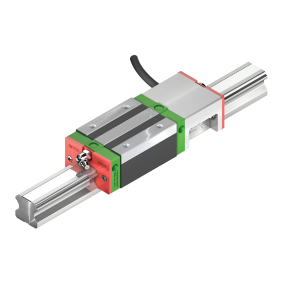
Figure 8.2 Scale drawing of the HGH20CA block including the MAGIC-PG housing Figure 8.2 shows an HGH20CA block. HIWIN MAGIC-PG modules are also available for the HGH25CA block. The dimensions of these two blocks are specified in table 8.1. It is also possible to use the modules with HG20 and HG25 block sizes (long type and flange type, see the "Linear Guideways"... -
Page 22: Technical Data Of The Magic Encoder
Technical data of the MAGIC encoder Table 8.2 Electrical and mechanical properties of the HIWIN MAGIC and HIWIN MAGIC-PG Electrical properties (analog) TTL (digital) Resolution Infinite, signal period 1 mm 1 μm Reference signal Periodic index impulse at a distance of 1 mm 0.85 V... -
Page 23: Technical Data Of The Magnetic Scale
Figure 8.4 Signals of the MAGIC encoder (TTL version) Technical data of the magnetic scale Table 8.3 Technical data of the magnetic scale Accuracy class ± 20 μm Period 1 mm Thickness (including double-sided 1.70 ± 0.10 mm adhesive tape) -
Page 24: Reference Switch
Cable Cable length Protective insulation, rated voltage 50 V Figure 8.5 Scale drawing 1 = switch state indicator of the reference switch HIWIN_Montageanleitung_MAGIC_V1.1_EN.doc - 10/2010 GETOtec Schwindstraße 9 Telefon: +49 (0)89 954164-10 info@getotec.de D-80798 München Telefax: +49 (0)89 954164-11 www.getotec.de... -
Page 25: Spare Parts And Item Numbers
8-08-0122 TTL, multi-index, cable length 5 m, open ends 8-08-0123 TTL, single index, cable length 5 m, open ends HIWIN MAGIC-PG HG20 encoder, open ends (including an 8-12-0093 screw set in each case) 8-08-0211 1V , multi-index, cable length 5 m... -
Page 26: Order Code For Pg Linear Guideway
Screw set for the MAGIC-PG 8-12-0093 Consisting of: 1x headless screw with M6x8 hexagonal socket 2x cylindric head screws with M2.5x20 hexagonal socket [13] 2x rounded head screws with M2.5x10 cross slot [10] 2x hex nut (low) M2.5 [12] 4x lock washer (Schnorr) Ø2.5... -
Page 27: Declaration Of Incorporation
Responsible for the documentation: Werner Mäurer Brücklesbünd 2 77654 Offenburg Product designation: HIWIN MAGIC and HIWIN MAGIC-PG distance measuring systems Year of manufacture: from 2010 The manufacturer hereby declares that this machinery, which is incomplete, meets the requirements of the Machinery Directive (2006/42/EC).
Need help?
Do you have a question about the MAGIC and is the answer not in the manual?
Questions and answers