Table of Contents
Advertisement
Quick Links
SERVICE &
PARTS MANUAL
High Output 2 : 1
Transfer Pump
GHO
Polyurethane Machinery Corp.
Headquarters: 1 Komo Drive, Lakewood NJ 08701
Manufacturing: 2 Komo Drive, Lakewood, NJ 08701
REVISION 3.0
Phone:732-415-4400
Fax: 732-364-4025
http://www.polymac-usa.com
Before installing the GHO Transfer Pump, carefully read all the technical and safety
documentation included in this manual. Pay special attention to the information in order to
know and understand the operation and the conditions of use of the GHO Transfer Pump.
All of the information is aimed at improving user safety and avoiding possible breakdowns
from the incorrect use of the GHO Transfer Pump .
Advertisement
Table of Contents

Summary of Contents for PMC GHO
- Page 1 Pay special attention to the information in order to know and understand the operation and the conditions of use of the GHO Transfer Pump. All of the information is aimed at improving user safety and avoiding possible breakdowns...
-
Page 2: Table Of Contents
INITIAL MACHINE SET-UP ....................9 INSTALLATION ........................10 OPERATION ........................12 DISASSEMBLY ........................13 PART IDENTIFICATION ..................... 15 TRANSFER PUMP ASSEMBLY (GHO) ..................15 DETAIL A .................................... 16 DETAIL B .................................... 17 DETAIL C .................................... 18 DETAIL D .................................... 19 AIR MOTOR ASSEMBLY (PU-04000-01) .................. -
Page 3: Warranty
PMC manufactured accessories delivered with the equipment (hereinafter “Product”) against defects in material or workmanship of the Product (hereinafter “Defect” or “Defective”) for a period of one (1) year from the date of first purchase as shown on the original PMC invoice (hereinafter “Warranty Period”). - Page 4 No Rights Implied: Nothing in the sale, lease or rental of any Product by PMC shall be construed to grant any right, interest or license in or under any patent, trademark, copyright, trade secret or other proprietary right or material owned by anyone;...
-
Page 5: Safety And Handling
GHO pump; you will provide a better opportunity for incident-free operation for a longer time, greater output and the possibility of detecting and resolving problems fast and simply. - Page 6 Service & Parts Manual IMPORTANT SAFETY INFORMATION The GHO 2:1 pump has been designed and built for the application of polyurea chemical systems, polyurethane foam chemical systems and some two-component epoxy systems. Always use liquids and solvents that are compatible with the unit. In the event of doubt, consult PMC technical service.
-
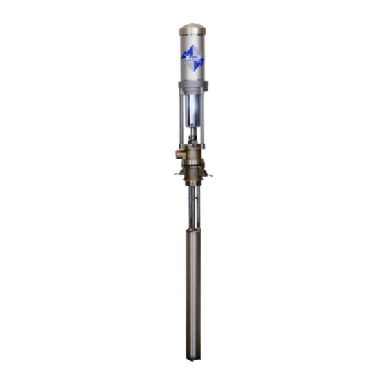
Page 7: Technical Specifications
¼ NPT (F) Fluid Output: ¾ NPT (F) 2.0 cfm per gallon – pumped @ 100 psi Air Consumption 124.67 cc/sec per liter pumped @ 689 kpa Weight 25 lbs/11.4 kg GHO Transfer Pump Figure 1 GHO-S Transfer Pump (Stubby) -
Page 8: Optional Equipment
Service & Parts Manual OPTIONAL EQUIPMENT Figure 2: Transfer Pump Air Hose Assembly Figure 3: Bung Adaptor PU-04000-F PU-04000-33 PU-04000-H Figure 5: Swivel Unions Figure 4: Material Supply Hose ¾ x 10’ A Supply Hose (1/2 NPT) PU-179-5 ¾ NPT x ½ NPT (F) PU-6157A-A-10 ¾... -
Page 9: Initial Machine Set-Up
Service & Parts Manual INITIAL MACHINE SET-UP Figure 6: Typical Installation for Classic Hydraulic Proportioner... -
Page 10: Installation
Figure 9: Installing Outlet Fitting 4. Install air lines as required. PMC recommends using a 3/8” ID or larger air line to deliver air to the transfer pump. Figure 10: Installing Air Line... - Page 11 The transfer pump pumps both resin and isocyanate. To reduce the possibility of inadvertently using the transfer pump with the wrong chemical, PMC recommends color coding the transfer pumps red for isocyanate and blue for resin.
-
Page 12: Operation
Service & Parts Manual OPERATION Daily Startup Procedures Keep Clear 1. Determine that the air needle valve is closed. of this area 2. Connect the air line quick disconnect coupler to the transfer pump. 3. Turn on the main air supply. 4. -
Page 13: Disassembly
Service & Parts Manual DISASSEMBLY 1. Place the transfer pump in a vice PRECAUTION: Hold in Vice Do not clamp the transfer by Standoff pump tightly. Figure 13: Mounting in Vice NOTE: It might be necessary to place a strap wrench around the lower end of the suction tube when removing the foot valve. - Page 14 Service & Parts Manual 4. Place a strap wrench around the lower end of the air cylinder and unthread. Use Strap Wrench Here Figure 16: Strap Location 5. Use a 5/16-inch diameter pin to keep the piston rod plunger from rotating. Unthread the piston. 6.
-
Page 15: Part Identification
Service & Parts Manual PART IDENTIFICATION TRANSFER PUMP ASSEMBLY (GHO) DETAIL PAGE... -
Page 16: Detail A
Service & Parts Manual DETAIL A TRANSFER PUMP ASSEMBLY (GHO) PART ITEM QTY DESCRIPTION NUMBER AIR CYLINDER CAP ASSEMBLY PU-04000-44 (PAGE 23) PU-04000-62 AIR CYLINDER AIR MOTOR AND PLUNGER TOP PU-04000-18 ASSEMBLY (PAGE 21) PU-04000-79 DOWEL PIN PU-04000-21 DISPLACEMENT PLUNGER... -
Page 17: Detail B
Service & Parts Manual DETAIL B TRANSFER PUMP ASSEMBLY (GHO) ITEM PART NUMBER DESCRIPTION PU-04000-88 O-RING 2-137 PU-04000-68 PTFE GASKET PU-04000-24 PUMP BODY, GHO PU-04000-26-X STUBBY PUMP BODY PU-04000-50 LOWER COMPRESSION TUBE PU-04000-91 O-RING 2-032 PU-04000-89 #8-32 SOFT TIP SET SCREW... -
Page 18: Detail C
Service & Parts Manual DETAIL C TRANSFER PUMP ASSEMBLY (GHO) ITEM PART NUMBER DESCRIPTION PU-04000-59 U-CUP COLLAR PU-04000-69 PISTON CUP PU-04000-41 PUMP SHAFT ASSEMBLY PU-04000-70 U-CUP PU-04000-67 WEAR RING PU-04000-90 3/4" SS BEARING BALL PU-04000-53 PISTON HOUSING... -
Page 19: Detail D
Service & Parts Manual DETAIL D TRANSFER PUMP ASSEMBLY (GHO) ITEM PART NUMBER DESCRIPTION PU-04000-91 O-RING 2-032 PU-04000-75 SUCTION TUBE FOOT VALVE ASSEMBLY PU-04000-45 (PAGE 24) PU-04000-40 SQUARE GASKET PU-04000-33 BUNG ADAPTER ASSEMBLY... -
Page 20: Air Motor Assembly (Pu-04000-01)
Service & Parts Manual AIR MOTOR ASSEMBLY (PU-04000-01) AIR MOTOR ASSEMBLY (PU-04000-01) ITEM QTY PART NUMBER DESCRIPTION PU-04000-11 AIR PISTON PU-04000-15 GASKET TOP PU-04000-03 UPPER AIR VALVE ASSEMBLY PU-04000-02 #10-32 X 1-5/16 SHCS PU-04000-08 SPACER 28/32 PU-04000-13 WEAWR RING PU-04000-04 SILICONE GASKET PU-04000-09 WEAR RING... -
Page 21: Air Motor And Plunger Top Assembly (Pu-04000-18)
Service & Parts Manual AIR MOTOR AND PLUNGER TOP ASSEMBLY (PU-04000-18) AIR MOTOR AND PLUNGER TOP ASSEMBLY (PU-04000-18) ITEM PART NUMBER DESCRIPTION PU-04000-01 AIR MOTOR ASSEMBLY (PAGE 20) PU-04000-60 PLUNGER TOP PU-04000-78 #10-32 X 3/8 SET SCREW PU-04000-80 O-RING 2-223... -
Page 22: Air Motor To Pump Coupling Assembly (Pu-04000-23)
Service & Parts Manual AIR MOTOR TO PUMP COUPLING ASSEMBLY (PU-04000-23) AIR MOTOR TO PUMP COUPLING ASSEMBLY (PU-04000-23) ITEM QTY PART NUMBER DESCRIPTION PU-04000-73 SPRING PU-04000-81 SQUARE O-RING PU-04000-84 U-CUP PU-04000-49 AIR CYLINDER BASE PU-04000-63 THREADED STANDOFF PU-04000-51 AIR CYLINDER MOUNTING FLANGE PU-04000-87 1/4-20 X 1 SHCS... -
Page 23: Air Cylinder Cap Assembly (Pu-04000-44)
Service & Parts Manual AIR CYLINDER CAP ASSEMBLY (PU-04000-44) AIR CYLINDER CAP ASSEMBLY (PU-04000-44) ITEM QTY PART NUMBER DESCRIPTION PU-04000-43 CAP AND BUMPER ASSEMBLY PU-04000-17 AIR CYLINDER CAP PU-04000-20 BUMPER PU-04000-72 SPRING PU-04000-81 SQUARE O-RING PU-04000-77 FIBER WASHER PU-04000-57 #10-32 X 1/2 PRESSURE RELIEF SCREW... -
Page 24: Foot Valve Assembly (Pu-04000-45)
Service & Parts Manual FOOT VALVE ASSEMBLY (PU-04000-45) FOOT VALVE ASSEMBLY (PU-04000-45) ITEM PART NUMBER DESCRIPTION PU-04000-55 FOOT VALVE HOUSING PU-04000-90 3/4" SS BEARING BALL PU-04000-93 E-RING 5133-75 PU-04000-92 SNAP RING N5000-106... -
Page 25: Tool Kit (Pu-04000-94)
Service & Parts Manual TOOL KIT (PU-04000-94) TOOL KIT (PU-04000-94) ITEM QTY PART NUMBER DESCRIPTION PU-04000-82 BALL VALVE PU-04000-83 AIR FITTING PU-04000-86 1/4-20 X 1/2 MACHINE SCREW PU-04000-66 GROUNDING LUG PU-04000-106 SPANNER PIN... -
Page 26: Manual Revisions
Service & Parts Manual MANUAL REVISIONS Revision Date Changes Approved P1 Changed Address to Komo Dr; P16 added air motor drawing to show gasket and 3 washers; 19-Mar-14 Vadams updated contents, page and figure numbers to reflect change Updated formatting, table of contents, and 20-Feb-15 Vadams part description illustrations.
Need help?
Do you have a question about the GHO and is the answer not in the manual?
Questions and answers