Table of Contents
Advertisement
Quick Links
WORLD HEADQUARTERS
CANADA
Yorkville Sound Limited
550 Granite Court
Pickering, Ontario
L1W 3Y8 CANADA
Voice: 905-837-8481
Fax: 905-837-8746
U.S.A.
Yorkville Sound Inc.
4625 Witmer Industrial Estate
Niagara Falls, New York
14305, USA
Voice: 716-297-2920
Fax: 716-297-3689
SERVICE MANUAL
EXM-MOBILES
SMT Disclaimer
Due to the complex nature of the use of SMT installed components
in Yorkville equipment, we highly caution all service technicians in
attempting to repair or replace SMT factory installed components.
Many of these components may be glued prior to initial soldering.
Replacing SMT components requires expensive
specialized de-soldering equipment and training.
Yorkville Sound will repair and replace defective SMT components
to ensure proper quality assurance and installation is maintained.
Manual-Service-EXM-MOBILES-00-1v0 • Feb 25/2022
Advertisement
Table of Contents

Related Manuals for YORKVILLE EXM-MOBILES


Summary of Contents for YORKVILLE EXM-MOBILES
- Page 1 Due to the complex nature of the use of SMT installed components 550 Granite Court 4625 Witmer Industrial Estate in Yorkville equipment, we highly caution all service technicians in Pickering, Ontario Niagara Falls, New York attempting to repair or replace SMT factory installed components.
-
Page 2: Important Safety Instructions
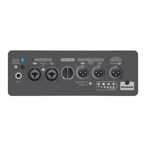
IMPORTA NT SA FETY INSTRUCTIONS This lightning flash with arrowhead symbol, within an The exclamation point within an equilatereal triangle is intended to alert the user to the presence equilateral triangle, is intended to alert the user to the presence of uninsulated “dangerous of important operating and maintenance (servicing) instructions in the literature accompanying voltage”... - Page 3 Full Range Pair ing : M A I N I N P U T S S U B L E V E L H I G H PA S S O U T P U T S O U T P U T Hold for 4 seconds Activ ity...
- Page 4 Specifications Active or Passive Active Program Power (watts) 100 watts, program (175 watts, peak) Measured Max SPL (C-Weighted, Max Hold) 116dB Continous, 122 dB Peak Frequency Response (Hz +/- 3dB) 47Hz-100Hz Crossover Frequency (Hz) 100 Hz Lowpass Cabinet Configuration Bass Reflex Driver Configuration 2x 8-inch LF woofer LF Driver(s)
- Page 5 Spécifications Active ou Passive Active Puissance Nominale (watts) 100 watts, programme (175 watts, crête) SPL maximum mesuré (pondéré C, maintien maximum) 116dB en continu, 122 dB en crête Réponse en fréquence (Hz +/- 3dB) 47Hz-100Hz Fréquence de coupure (Hz) Passe-bas 100 Hz Configuration de l'enceinte Bass Reflex Configuration des haut-parleurs...
- Page 6 EXM MobileSUB Block Diagram for DESIGNE D & MANUFACTURED BY Y O RKVIL L E S O UN D INPUT AUX IN WIRELESS LINK HP OUT 1/8-inch Bluetooth 8-inch Woofer 100Hz LEVEL POWER 100W 100Hz 8-inch Woofer INPUT HP OUT BL O C K-EX M-MO BI L ES-0 0 -1 v 2...
- Page 7 M1951 02 P1 Parts Reference List 8/5/2021 YS # Description YS # Description YS # Description YS # Description YS # Description 7811 100U 25V 20%CAP 8X5.4 SMT ELE 5979 100N 50V 5%CAP 0805 SMT X7R 4140 XLR MALE PCB MT VERT 24MM A-SERIES 7646 W125 681R 0805 SMT RES...
- Page 8 M1951 02 P2 Parts Reference List 8/5/2021 YS # Description YS # Description YS # Description YS # Description YS # Description 8550 BM83 BLUETOOTH DIGITAL SMT MOD 8516 TL062 DUAL OPAMP LOPWR SMT SOIC8 6627 LM3409HV PFET BUCK SMT IC VSSOP-10P 7661 LM393D DUAL COMPARATOR SMT SO-8 7719...
-
Page 9: Input Section
Input - 85 - 240 VAC IEC_RECT PowerSupply +V_In Battery -12V -12V Bat+In Bat_Gnd Bat+In W11:1 BatTemp +12V +12V BatTemp W11:2 Bat-In Bat-In W11:3 ChgLED 9708 Power Supply +BatSw PowerIn V+_In V+_In W2:1 PsGnd PsGnd W2:2 PowerSupply.SchDoc In-Out Input.SchDoc Power Amp BT_R BT_L AmpOut-... - Page 10 U2:1 {Function} {Function} 8516 RAD .2in RAD .2in 4140 7828 7828 U9:4 U9:3 TL062 W100 EXM-MobileSub 0805 Yorkville Sound Ltd. Product(s): CDSF4148 20K0 D1005 100N 550 Granite Court Description: Battery Powered Subwoofer Pickering, ON 100N +12V 0805 PCB#: M1951 Rev#:...
-
Page 11: Battery Status
+V_In_ MMBT3906LT1 +V_In_ Bat+In W125 7805 0805 SOT-23 R136 SOT23 R203 47K5 BAT750 0805 0805 +BatSw R220 R259 0805 0805 R260 3920 3920 7.21 R261 LD4:2 3920 7840 6.82 0805 0805 R265 3920 11760 6.43 562R0 562R0 1210 12970 6.23 0805 0805 7032... - Page 12 +VSw BSC060P03NS3E G +V_In +VSw +V_In +VPS +VSw V+_In +VSw V+_In R138 7006 R294 +vToAmp 100K0 2494 47K5 4X4mm 0805 Rad .2 0805 47K5 +VPS PG-TDSON-8-1 0805 R210 10K0 R188 R202 Power 0805 100K0 Enable Enable 10K0 0805 PMLL4148 0805 +BatSw SOD80 R218...
-
Page 13: Power Amp
+V_PWR MODSEL PVCC -V_PWR PVCC 31 8x8mm 0805 0805 TPA3116D2 R221 6690 475K 0805 R209 C163 TSSOP32P -V_PWR Enable Enable W125 5K60 150N 0805 0603 FAULTZ BSPR R168 150N W100 0603 200R RINP R250 0805 W100 RINN OUTPR GND 28 200R 0805 PLIMIT... - Page 14 Tag_Connect - UART PCB connections - W5 5v In 9,7,3 BT_GND P0_0 E:\My Documents\AD\M3915TestFixture P2_4 470P 0603 W125 562R0 R112 0805 W125 BT_Gnd 8516 562R0 R104 0805 BT_Audio_R RFS1 P0_0 / UART_TX_IND W100 +AdapIn 200R SCLK1 P3_7 / UART_CTS R116 1206 TL062 0805...
- Page 15 PCB ASSEMBLY DOCUMENTATION SPECIAL PRODUCTION NOTES Add soldermask dots to the two threaded spacers. The input section needs to be air tight. All vias and part holes must be filled with solder. Heatsink Assembly (PCB Finishing) 3) Place Z1891 HS on top of U8. 1) Remove the kapton tape from the two spacers.
- Page 16 150N 47K5 150N 100N 4148 C165 100N C174 5K60 R126 R138 R100 R112 B160 47K5 150P R200 R209 10K0 475K Yorkville Yorkville 10UH 5K60 10K0 R249 180P R255 1K21 2021 2021 TL062 100R 100N R124 100K0 1K21 TJH2 SNL1 220U R215 Insert two 8535 spacers at the crosshairs.
- Page 17 PCB ASSEMBLY DOCUMENTATION SPECIAL PRODUCTION NOTES Add soldermask dots to the two threaded spacers. The input section needs to be air tight. All vias and part holes must be filled with solder. Heatsink Assembly (PCB Finishing) 3) Place Z1891 HS on top of U8. 1) Remove the kapton tape from the two spacers.
-
Page 18: Change History
DESIGN HISTORY AND INFORMATION CHANGE HISTORY POTENTIOMETERS AND KNOBS POTENTIOMETERS/SWITCHES AND KNOBS FUNCTION POT/SW YS# STYLE KNOB# DATE VER# DESCRIPTION OF CHANGE Sub LEVEL 4434 10043 25-Mar-2021 Released For Production 3439 8637 03-NOV-2021 9712 R105 IK0 YS#7621 replaced with 10K0 YS#7625. Power 3522 8637... -
Page 19: Button Operation
To get the full Owner’s Manual please visit our website at http://www.yorkville.com/manuals/ or, if you need a printed version call 905-837-8777 Printed In Canada QuickStart-EXM-MOBILES-00-1v0 • YS#QSTART-MOBILES • April 26, 2021... -
Page 20: Fonctionnement Des Boutons
Assurer de charger votre EXM pour 5 heures avant la première utilisation avec la batterie! met fin à la connexion sans fil stéréo. http://www.yorkville.com/manuals/ Pour obtenir le manuel de utilisateur visitez notre site Web à ou, si vous avez besoin d’une version imprimée appelez-nous au 905-837-8777... - Page 21 Yorkville Sound 550 Granite Court Pickering, Ontario Canada L1W 3Y8 www.yorkville.com Auto Attend: (905) 837-8550 Fax: (905) 837-8746...
Need help?
Do you have a question about the EXM-MOBILES and is the answer not in the manual?
Questions and answers