
Summary of Contents for Vex Robotics Victor SPX
- Page 1 217-9191-751 Victor SPX User Guide Victor SPX User Guide vexpro.com ctr-electronics.com Copyright 2018, VEX Robotics Inc., Cross the Road Electronics Updated: 2021-11-29...
-
Page 2: Table Of Contents
Thermal Performance ................................12 Frequently Asked Questions: ..............................13 Troubleshooting ..................................16 FCC Compliance Statement (United States) ..........................19 ICES-003 Compliance Statement (Canada) ..........................19 Revision History ......................................19 vexpro.com ctr-electronics.com Copyright 2018, VEX Robotics Inc., Cross the Road Electronics Updated: 2021-11-29... -
Page 3: The Victor Spx At A Glance
(vexrobotics.com) & Cross the Road Electronics (ctr-electronics.com) that allows for fine control and high performance of brushed DC motors in competition robotics applications. The Victor SPX handles high current loads with minimal voltage drop and heat generation. Its linear output and Brake/Coast options allow for precise motor control, making it well suited for all FRC motor applications from drivetrains to shooter wheels. -
Page 4: Installing The Victor Spx
PWM signal. In many cases, the output leads of the Victor SPX will not be long enough to reach the motor it is controlling, so an extension cable will be required. Extension cables should be made using appropriately sized wire and connected using properly crimped connectors. -
Page 5: Controlling The Victor Spx
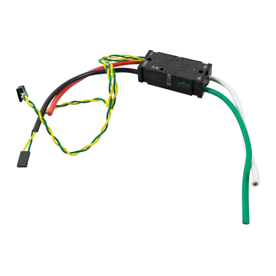
CAN bus Using the CAN bus to control the Victor SPX allows users to take full advantage of all its features. To wire the CAN bus, connect a yellow signal wire to the CAN terminal marked “H” on the NI roboRIO and connect a green signal wire to the CAN terminal marked “L”... -
Page 6: Pwm
Either of the Victor SPX’s built-in CAN bus wires can be used to control the device using PWM. In addition, one set of twisted pair wires have a male PWM connector while the other has a female PWM connector. -
Page 7: Mounting The Victor Spx
VEXpro ARM9 Microcontroller To connect a Victor SPX with any of the above VEX microcontrollers, simply plug the Victor SPX’s male PWM connector into the desired motor port on the microcontroller with the white (signal) wire on the “inside” of the microcontroller. -
Page 8: Strain Relief
An important yet frequently forgotten aspect of wiring is strain relief. All electrical connections should be isolated from any pulling or tugging that may result in a poor connection. Once the Victor SPX is fully wired, zip ties should be used to ensure that all electrical connections are protected. -
Page 9: Additional Information
Additional Information Brake & Coast Modes The Victor SPX has two modes: Brake and Coast. When a neutral signal is applied to the Victor SPX in Brake mode, the motor will resist rotation, especially high-speed rotation. This is accomplished by essentially shorting the motor leads, which causes a Back Electromotive Force (Back-EMF) to resist the rotation of the motor. -
Page 10: Calibration
“max” and “min” signals that may not correspond to the same Victor SPX outputs. Calibrating the Victor SPX allows it to adjust for these differences so that a “max” signal results in a “max” output. Calibrating can also correct issues caused by joysticks or gamepads with off-center neutral outputs. -
Page 11: Blink Codes
2) (1X) Status LED will blink followed shortly by the other with a long pause before repeating. The “direction” of the blink indicates the Talon SRX’s current state. vexpro.com ctr-electronics.com Copyright 2018, VEX Robotics Inc., Cross the Road Electronics Updated: 2021-11-29... -
Page 12: Thermal Performance
To evaluate the Victor SPX’s thermal performance, a 40A load was applied using CIM motors and a dynamometer. Before the test, a thermocouple was attached to the top of the Victor SPX PCBA. The test was run for 15 minutes at 50% duty cycle. After the motor controller returned to room temperature, the test was re-run at 100% duty cycle. -
Page 13: Frequently Asked Questions
Q: Does the Victor SPX require a fan? A: The Victor SPX does not require a fan for typical FRC use, but if the robot is being used for practice or many back to back matches it is a good idea to use a fan to cool the Victor SPX. - Page 14 As documented in the DW CAN bus specification, both daisy chain or a designed master cable harness meets the specification’s documented topology (diagram below). vexpro.com ctr-electronics.com Copyright 2018, VEX Robotics Inc., Cross the Road Electronics Updated: 2021-11-29...
- Page 15 CAN bus specification. This nonstandard implementation requires careful study and analysis of the candidate bus cable, which is typically beyond the capabilities of a typical FRC team. vexpro.com ctr-electronics.com Copyright 2018, VEX Robotics Inc., Cross the Road Electronics Updated: 2021-11-29...
-
Page 16: Troubleshooting
2. If Status LEDs remains off, check +V or GND connections for voltage and proper polarity. 3. If Status LEDs blink ORANGE, the speed controller is probably damaged. The final test to determine if the Victor SPX is damaged to to replace it with another Victor SPX that is known to function properly. - Page 17 Problem: Possible internal damage. Possible Solutions: If the Status LEDs on the Victor SPX are operating properly and there is no output, the Victor SPX may be internally damaged. This condition is typically caused by a short circuit on the output or there has been an over-current condition that caused a failure.
- Page 18 Problem: No input power or possible internal damage. Possible Solutions: If the Status LEDs on the Victor SPX are not operating properly and there is no output, the Victor SPX may be internally damaged. This condition is typically caused by no input power or a reversed polarity on the input.
-
Page 19: Fcc Compliance Statement (United States)
Cet appareil numérique de la classe B est conforme à la norme NMB-003 du Canada. Revision History: 2018/05/31 – Initial Public Release 2021/11/29 – Added PWM voltage and current info vexpro.com ctr-electronics.com Copyright 2018, VEX Robotics Inc., Cross the Road Electronics Updated: 2021-11-29...
Need help?
Do you have a question about the Victor SPX and is the answer not in the manual?
Questions and answers