Table of Contents
Advertisement
Quick Links
DESCRIPTION, INSTALLATION, OPERATION, AND
MAINTENANCE MANUAL
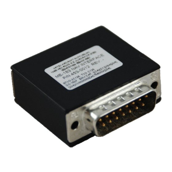
ME-183 NAV INTERFACE 453-0012
Document No.: 570-0001 Rev. -
Cobham Avionics
Artex Products
Artex Aircraft Supplies, Inc.
doing business as Cobham Avionics
14405 Keil Road NE Aurora, Oregon 97002 USA
Phone 503-678-7929, Fax 503-678-7930
E-mail
info@artex.net
www.artex.net
Advertisement
Table of Contents

Summary of Contents for ARTEX Cobham ME-183 NAV
- Page 1 DESCRIPTION, INSTALLATION, OPERATION, AND MAINTENANCE MANUAL ME-183 NAV INTERFACE 453-0012 Document No.: 570-0001 Rev. - Cobham Avionics Artex Products Artex Aircraft Supplies, Inc. doing business as Cobham Avionics 14405 Keil Road NE Aurora, Oregon 97002 USA Phone 503-678-7929, Fax 503-678-7930 E-mail info@artex.net...
- Page 2 LIST OF AFFECTED PAGES PAGE # DATE REASON FOR CHANGE TITLE 07/14/09 07/14/09 07/14/09 07/14/09 07/14/09 07/14/09 07/14/09 07/14/09 07/14/09 07/14/09 07/14/09 07/14/09 07/14/09 07/14/09 07/14/09 07/14/09 07/14/09 07/14/09 07/14/09 07/14/09 07/14/09 Page 2 of 21...
- Page 3 REVISION HISTORY REVISION ENGINEERING CHANGE ORDER DATE RELEASE 07/14/09 Page 3 of 21...
-
Page 4: Table Of Contents
TABLE OF CONTENTS 1. INTRODUCTION........................5 ......................5 YSTEM DVANTAGES ......................6 YSTEM ESCRIPTION ......................6 PERATIONAL VERVIEW ........................7 OMPATIBILITY 2. INTEGRATION........................8 ....................8 UTPUT EQUIREMENTS NMEA 0183 S ..............8 ENTENCE TRUCTURE EQUIREMENTS 3. OVERVIEW ........................... 9 ....................9 EGULATORY EQUIREMENTS ........................9 NSTALLATION (ESD) P ................9 LECTROSTATIC ISCHARGE... -
Page 5: Introduction
ME-183 NAV Interface (ME-183 NAV). The ME-183 NAV relays latitude and longitude position data to the ELT for incorporation into the 406 MHz Search and Rescue (SAR) satellite message. The ME-183 NAV is designed as a retrofit accessory for Artex ME406 Series ELT installations. -
Page 6: System Description
Figure 1-2: ME-183 NAV Interface System Integration Block Diagram Installation of the ME-183 NAV requires an on-board navigation system (GPS) supporting NMEA 0183 output, in addition to an Artex ME406 ELT system. The GPS receives satellite signal information, calculates latitude and longitude position, and sends the position data to the ME-183 NAV. -
Page 7: Compatibility
• The ELT transmits a default message if it does not receive valid position data. • Compatibility The ME-183 NAV is compatible with the following Artex ME406 Series ELTs: ME406 ELT – 453-6603 • ME406 HM ELT – 453-6604 •... -
Page 8: Integration
The ME-183 NAV is compatible with NMEA 0183. Artex recommends the use of a dedicated GPS data output channel for the ME-183 NAV. Data Output Requirements... -
Page 9: Overview
OVERVIEW This section provides an installation overview and should be reviewed by personnel performing the work. Regulatory Requirements TSO C126, Paragraph D “The conditions and tests required for TSO approval of this article are minimum performance standards. It is the responsibility of those desiring to install this article on a specific type or class of aircraft to determine that the aircraft installation conditions are within the TSO standards. -
Page 10: Installation
The ELT must be programmed with a long message (location protocol), if necessary, before installing the ME-183 NAV. ELT reprogramming may be accomplished by an authorized service center or by using an Artex ME406 Reprogramming Adapter (455- 6600). Installation Instructions The following subsections provide installation guidelines and instructions. -
Page 11: Wiring Diagrams
Make a “Drip Loop” in the remote switch harness connection to the ME-183 NAV • to divert moisture from the DB15 plug. NOTE: A drip loop is an extra length of cable formed into a U-shaped bend just before the plug. Water or other fluids flow down to the bottom of the loop and drip off, diverting them away from the plug. -
Page 12: Gps Data Output Interface With Remote Switch Harness
FROM GPS DATA OUTPUT DB15 NOTE: GPS GROUND MUST BE REMOTE SWITCH PLUG COMMON TO AIRCRAFT GROUND MOLEX PLUG GPS TX RESET 1 RESET 2 UN-SWITCHED EXTERNAL ON POWER GSW0 +14V +28V GSW1 LIGHT GROUND NOTE: PINS 6 & 9 AUDIO POWER ARE INTERNALLY RED+... -
Page 13: Db15 Plug Replacement
Provide adequate strain relief for the conductor. d) Reassemble the back shell in accordance with Subsection 4.3.4, beginning with Step 8. NOTE: Artex recommends sealing the plug back shell in accordance with Subsection 4.3.5. 5. Cut off the harness DB15 plug. - Page 14 6. Solder a jumper between Pins 5 and 12 of the DB15 plug (Figure 4-6). 7. Solder the conductors into the solder cups of the DB15 plug (Figure 4-6). NOTE: Check conductor color coding and pin relationships noted in Subsection 0, Step 6, to ensure proper connection of the conductors.
-
Page 15: Db15 Plug Back Shell Sealing
12. Fit the other housing half into place, taking care to align the thumbscrews, bracket washers, grommet, and plug. 13. Screw the housing halves together using the long, fully-threaded screws and nuts supplied as part of the D-Sub housing kit. 14. -
Page 16: Me-183 Nav Interface Testing
ME-183 NAV INTERFACE TESTING The purpose of this testing is to verify integrity of the ELT system after ME-183 NAV installation. This section also discusses the option of verifying position data transmission using a beacon test set. Self-Test The following procedure initiates an ELT self-test routine to verify integrity of the ELT system. -
Page 17: Position Data Verification
G-switch loop error ELT battery usage over one hour Position Data Verification Artex does not require this test be performed; any problem with received position data will be indicated by the 5-pulse error (Table 5-1) during self-test (Subsection 5.1.2). CAUTION: Artex only recommends this test be performed if the 406 MHz signal can be properly shielded inside a screen room or container. -
Page 18: Periodic Maintenance
PERIODIC MAINTENANCE The following subsections describe periodic maintenance and testing requirements and procedures for the ME-183 NAV. Comply with these requirements at the same time periodic maintenance and testing is performed on the ELT system. Inspection WARNING: It is possible to inadvertently activate the ELT when working around the ELT and/or removing and installing the ME-183 NAV. -
Page 19: Specifications And Approvals
SPECIFICATIONS AND APPROVALS The following subsections provide specifications and approval information for the ME-183 NAV. Environmental Requirements and Specifications Table 7-1 lists the environmental conditions testing required by RTCA DO-160F, “Environmental Conditions and Test Procedures for Airborne Equipment”. Table 7-2 provides the ME-183 NAV environmental specifications. -
Page 20: Physical Specifications
Table 7-2: Environmental Specifications PARAMETER CHARACTERISTICS Storage Temperature -55° C to +85° C (-67º F to +185º F) Operating Temperature -40° C to +70° C (-40º F to +158º F) Altitude 50,000 ft (15,240 m) Vibration 10 G from 5 Hz to 2,000 Hz Shock 500 G for 4 ms / 100 G for 23 ms Humidity... -
Page 21: Approvals
Approvals The ME-183 NAV is manufactured and approved under the following regulatory requirements: FAA TSO-C126, 406 MHz Emergency Locator Transmitter (ELT) • ETSO-2C126, 406 MHz Emergency Locator Transmitter (ELT) • RTCA DO-160F, Environmental Conditions and Test Procedures for Airborne • Equipment RTCA DO-178B, Software Considerations in Airborne Systems and Equipment •...
Need help?
Do you have a question about the Cobham ME-183 NAV and is the answer not in the manual?
Questions and answers