Advertisement
Available languages
Available languages
Quick Links
Attach the mount to begin installation. See the mount manual for
instructions. Do not assemble plow blade or push tubes until the mount is
installed.
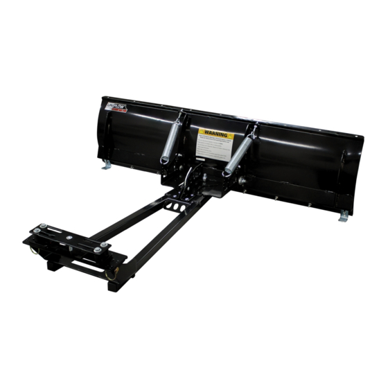
Includes:
1. 60" UniPlow HD Blade x 1
2. Reversible Wear Bar x 1
3. Pivot Plate x 1
4. Push Tube x 1
5. Tube Plate x 1
6. Pivot Handle Plate (RH) x 1
7. Pivot Handle Plate (LH) x 1
8. Pivot Handle x 1
9. Safety Pin x 2
10. 5/8"-11 x 1.75" Hex Bolt x 1
Plow Safety
Read this manual thoroughly before operating your plow. Failure to follow instructions could result in death, serious injury
or property damage. If you have questions regarding safe installation and/or use of your plow, contact customer service at
(651) 358-1862 on regular business days Monday-Friday from 8am-5pm CST, or e-mail service@extrememax.com.
Read, Follow, and Save These Instructions.
Warnings:
• UniPlow contains heavy components. Exercise extreme caution during assembly and mounting to avoid injury.
• Wear appropriate personal protective equipment at all times, including ANSI approved eyewear.
• Ensure the blade is locked into position and not pivoting freely before plowing.
• Plow is not for use by children. Do not use plow near children or allow children to play on the plow.
• Plow is not for use by inexperienced ATV operators.
• Never stand or ride on the plow. Always mark intended plow areas prior to snowfall to prevent accidental property damage
or injury caused by collision with unmarked hazards.
• Take care when installing plow springs. They will be under tension.
• Use care when lifting components into place.
• Make sure that all nuts and bolts are tightened per installation instructions.
• Never operate this product with missing or damaged parts.
• Do not exceed 5 mph while plowing snow or operating ATV with plow attached, even with the blade fully raised.
• Drive slowly over bumpy and rough terrain, driving fast could cause damage to winch or plow.
• Never raise the plow above point of contact as it could cause damage to machine, plow or winch.
• Always perform regular inspections and maintenance on plow tubes and hardware before use.
• Operate with extreme caution on slopes, steep grades, and rough terrain.
• Be aware of any possible hidden objects under the snow.
• Do not ram plow blade into snow piles.
• Know and follow all local snow removal and noise rules and restrictions. Never pile snow outside your property or on
streets or sidewalks. Keep areas around fire hydrants, mailboxes, water drains, and electrical boxes clear of snow and never
pile snow in a way that obstructs their access.
Customer Service: service@extrememax.com | www.extrememax.com
60" UniPlow HD
Assembly & Operating Instructions
11. 5/8" Star Washer x 1
12. 5/16"-18 x 1" Carriage Bolt x 1
13. 5/16"-18 Flanged Lock Nut x 5
14. 5/8"-11 x 1.5" Carriage Bolt x 2
15. Pitch Bushing x 2
16. 5/8" Fender Washer x 4
17. 5/8"-11 Lock Nut x 3
18. 7/16"-14 x 0.75" Socket-Head Cap
Screw x 2
19. 7/16"-14 Lock Nut x 2
5500.5094 - Plow W/ UniMount
5500.5109 - Plow F/ Polaris Sportsman 570
5500.5112 - Plow F/ Cam-Am Outlander
20. 5/16"-18 x 1.5" Carriage Bolt x 1
21. 5/16" x 1.25" Fender Washer x 2
22. Pivot Lever Spring x 1
23. Plow Spring x 2
24. Eyebolt x 2
25. 5/16" Flat Washer x 4
26. 5/16"-18 Hex Nut x 4
27. Skid Pad x 2
28. 5/16"-18 x 1.25" Carriage Bolt x 9
29. 5/16"-18 Lock Nut x 9
1
3518ex0121
Advertisement

Related Manuals for Extreme Max 5500.5094

Summary of Contents for Extreme Max 5500.5094
- Page 1 60” UniPlow HD Assembly & Operating Instructions 5500.5094 - Plow W/ UniMount Attach the mount to begin installation. See the mount manual for 5500.5109 - Plow F/ Polaris Sportsman 570 instructions. Do not assemble plow blade or push tubes until the mount is 5500.5112 - Plow F/ Cam-Am Outlander...
-
Page 2: Warranty
The sole remedy under this warranty is at the discretion of manufacturer: the replacement of the same or similar product, or the refund of the original purchase price. Extreme Max™ is not responsible for any consequential or incidental damages. Any and all freight charges to handle warranty claims are the responsibility of the consumer. Extreme Max™... - Page 3 Push Tube Assembly 1. Locate the push tube (4) and pivot plate (3). Place the pivot plate on top of the push tube and align the large center bolt hole with the matching hole at the narrow end of the push tube. From the bottom, insert the 5/8”-11 x 1.75”...
- Page 4 6. On the bottom of the push tube assembly, locate the spring mounting tab. Attach the pivot lever spring (22) from this tab to the hole on the bottom of the pivot handle. Plow Assembly 1. Attach the entire push tube assembly to the UniPlow blade. Align the large bolt holes in the side of the pivot plate with the bolt holes at the bottom of the two center blade braces.
- Page 5 60” UniPlow HD Instructions De Montage Et D’utilisation 5500.5094 - Plow W/ UniMount Fixez le support pour commencer l’installation. Voir le manuel de montage pour les instructions. Ne pas assembler la lame de charrue ou les tubes- 5500.5109 - Plow F/ Polaris Sportsman 570 poussoirs avant que le support ne soit installé.
-
Page 6: Garantie
Extreme Max™ n’est pas responsable des dommages indirects ou accessoires. Tous les frais de transport pour traiter les demandes de garantie sont à la charge du consommateur. Extreme Max™ n’est pas responsable des éventuels frais de main-d’œuvre. - Page 7 Assemblage Du Tube Poussoir 1. Localisez le tube de poussée (4) et la plaque pivotante (3). Placez la plaque pivot sur le tube de poussée et alignez le grand trou du boulon central avec le trou correspondant situé à l’extrémité étroite du tube de poussée.
- Page 8 6. Au bas du tube de poussée, repérez la languette de montage du ressort. Fixez le ressort du levier de pivot (22) de cette languette au trou situé au bas de la poignée de pivot. Assemblée De Charrue 1. Fixez l’ensemble du tube de poussée à la lame UniPlow. Alignez les grands trous de boulon situés sur le côté de la plaque pivot avec les trous de boulon situés au bas des deux entretoises de lame centrales.
- Page 10 26” Approx...
- Page 16 26” Approx...
Need help?
Do you have a question about the 5500.5094 and is the answer not in the manual?
Questions and answers