Table of Contents
Advertisement
Quick Links
2022/03/16 04:45
MS2000, MFC2000 and RM2000 OPERATION
Front Panel Controls
XY Joystick
The XY Joystick is spring loaded to return to a zero movement center when not in use. The speed at
which the stage moves is linear function of the degree to which the joystick is pushed away from the
center. The direction of deflection can be controlled by the settings of the DIP switches on the back
panel of the box (see
speed range of the joystick. In the high-speed range, the stage will travel up to the maximum speed
of the motors; in the low-speed range, the speed for maximum deflection is reduced to 5 – 10% of
maximum speed. The speed settings for the joystick may be programmed and saved in firmware. See
the
JSSPD
command.
Command Encoder Knob
The Command Encoder Knob is usually used to control the Z-axis stage. The relative speed of the
knob can be set with the
to any axis by using the JS command.
Zero Button
The Zero Button allows the user to set all three axes coordinates to zero. Upon pressing the button,
the LCD will display the change. Pressing the button also cancels any and all serial-controlled
movement commands. The zero button also acts as a HALT button to stop undesired motion. Pressing
the zero button briefly will halt motion and zero the coordinates; pressing and holding down the zero
button for more than 1 second will halt motion, but not alter the coordinate settings.
Home Button
The Home Button sends the stage back to the zero coordinates.
@ Button
The @ Button is programmed for special functions. On most controllers this button is used with the
Multi-Point Save/Move feature (see
Applied Scientific Instrumentation - https://asiimaging.com/docs/
1/18
Note: MFC2000 controllers lack a joystick.
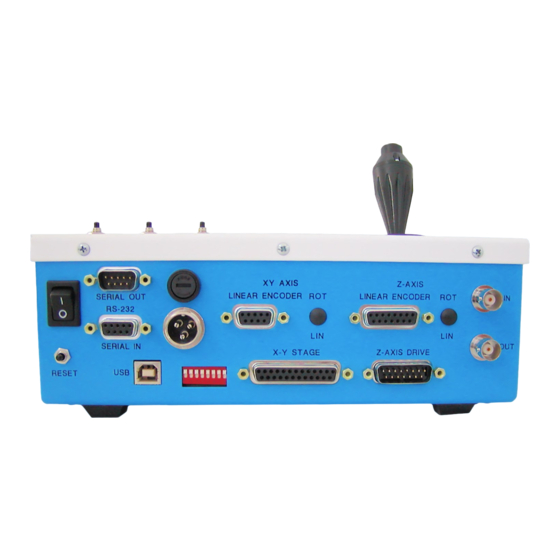
Back Panel
Controls). Depressing the button on top of the joystick will toggle the
JSSPD command
and saved in firmware. The command knob can be attached
Special Functions
MS2000, MFC2000 and RM2000 OPERATION
below).
Advertisement
Table of Contents

Subscribe to Our Youtube Channel
Related Manuals for ASI MS2000

Summary of Contents for ASI MS2000
- Page 1 2022/03/16 04:45 1/18 MS2000, MFC2000 and RM2000 OPERATION MS2000, MFC2000 and RM2000 OPERATION Front Panel Controls XY Joystick Note: MFC2000 controllers lack a joystick. The XY Joystick is spring loaded to return to a zero movement center when not in use. The speed at which the stage moves is linear function of the degree to which the joystick is pushed away from the center.
-
Page 2: Lcd Screen
LCD Screen Note: MS2000 and RM2000 have a 4-line LCD . MFC2000 controllers only have a two line LCD. The Liquid Crystal Display (LCD) screen shows the current position coordinates of the axes with status information displayed to the right. - Page 3 2022/03/16 04:45 3/18 MS2000, MFC2000 and RM2000 OPERATION 4 line version 2 line version The status line at the bottom of the display indicates the command set (H high or L low), the XY encoder mode (R rotary or L linear), and the Z encoder mode (R rotary or L linear). The next two numbers show the next position to move to for ring buffer, and the number of positions stored,...
-
Page 4: Back Panel
Please note that the Windows 10 Universal drivers do not work with ASI controllers; if you are running with Windows 10 OS, use the drivers for Windows 7/8/8.1. After the drivers are installed, you can check the communication between your computer and the controller by using your computer’s Device Manager. -
Page 5: Power Input
2022/03/16 04:45 5/18 MS2000, MFC2000 and RM2000 OPERATION powering up the controller, you will see COM1 and COM2 after powering it up.) The USB drivers on your computer create a virtual serial port whenever the computer is connected to a powered-up controller. This virtual serial port operates like an RS-232 port as described below. -
Page 6: Reset Button
Last update: 2021/12/20 16:41 ms2000_operation https://asiimaging.com/docs/ms2000_operation Two BNC connectors are provided, labeled IN and OUT. The connectors are wired to the internal board connector SV1. The IN connector is usually wired to IN0, the buffered TTL input channel. On piezo Z- axis (PZ_* Firmware) systems, the OUT connector is connected to the analog DAC output that is used for control of the piezo system with a 0-10v analog signal (3mA max). -
Page 7: Special Functions And Features
2022/03/16 04:45 7/18 MS2000, MFC2000 and RM2000 OPERATION Switch 4 Switch 5 Baud Rate DOWN 28800 DOWN DOWN 115200 Special Functions and Features Several special features have been incorporated into the stage control firmware beginning with version 6.0a. Several of these functions are standard on every controller, others are only supported with special hardware modifications or options;... - Page 8 TTL command. † These modules are often included in standard builds. If you see something you want but don’t have, contact ASI. Power Down Coordinate Save Beginning with firmware version 8.1, powering down the MS 2000 controller will automatically cause the current positions to be saved to non-volatile memory so they can be restored upon startup.
- Page 9 2022/03/16 04:45 9/18 MS2000, MFC2000 and RM2000 OPERATION Axis STATUS changes at end of Consequence of MAINTAIN move Description setting a WAIT code [MA] time[WT] BUSY BUSY Default – HYSTERESIS Motor and servo ε< Finish turns off when position error is less than ε...
- Page 10 Last update: 2021/12/20 16:41 ms2000_operation https://asiimaging.com/docs/ms2000_operation Constant Velocity Moves – (with firmware Version 8.1+) The MS 2000 controller now uses a full closed loop trajectory driven algorithm for all commanded moves. This means that the move velocity is controlled as part of the digital feedback loop. Many users need to have high precision slow speed control.
- Page 11 The TTL_REPORT_INT firmware module allow for external TTL synchronized position reporting. The position reports are sent to the auxiliary serial port on the MS 2000 WK in a binary format so that rapid, low jitter position reporting is possible for real-time positioning tasks. Contact ASI for details. Tracking Features ASI’s PhotoTrack system uses the TRACKING firmware module along with hardware available from ASI...
-
Page 12: Saved Parameters
The configuration flags are usually only changed when the controller is first set up for a particular set of hardware, when new firmware is loaded using the ASI Updater, or when changing between linear and rotary encoder for the stage. When a configuration flag is changed, it is immediately saved in nonvolatile memory;... - Page 13 2022/03/16 04:45 13/18 MS2000, MFC2000 and RM2000 OPERATION persistent using the “SS Z” command, which saves all parameter settings to nonvolatile flash memory. Users wishing to make a one-time permanent change to a parameter setting can use a terminal program to communicate with the controller, make the parameter change, and then make the change persistent with the “SS Z”...
-
Page 14: Back Panel Connector Pin-Outs
Internal Jumper JP2 selects the encoder signals that are counted during scanning. JP2 1-2 selects the X-axis; JP2 2-3 selects the Y-axis. Please contact ASI if you need assistance configuring the controller for special functions. Back Panel Connector Pin-outs https://asiimaging.com/docs/... - Page 15 2022/03/16 04:45 15/18 MS2000, MFC2000 and RM2000 OPERATION X-Y Stage DB-25F Connector PIN SIGNAL INFORMATION X Mot - X Motor - X GND X Encoder Ground X Enc Ch A X Encoder Channel A Y Mot - Y Motor -...
- Page 16 Last update: 2021/12/20 16:41 ms2000_operation https://asiimaging.com/docs/ms2000_operation Z-Axis Drive & Optional F-Axis DB-15M Connector SIGNAL INFORMATION Z Enc Ch B Z Encoder Channel B Ground CLTCH Clutch (+24V) Z Mot + Z Motor + F Enc Ch A F Encoder Channel A Z Lim U Z Upper Limit F Lim U...
-
Page 17: Electrical Characteristics
2022/03/16 04:45 17/18 MS2000, MFC2000 and RM2000 OPERATION XY Axis Linear Encoder (optional) DB-9M Connector SIGNAL INFORMATION N.C. Not Connected Z Axis Linear Encoder (optional) DB-15F Connector SIGNAL INFORMATION Z Enc Ch A Z Encoder Channel A Signal Ground Z Enc Ch B... - Page 18 With either the Keyspan or the Serial Card, you connect the device to the controller via a serial null modem cable. A serial null modem cable is furnished with each ASI controller and widely available at computer stores. Note that if the words “NULL MODEM” are not stamped on the connectors of a serial cable, it is probably not a null modem cable.
Need help?
Do you have a question about the MS2000 and is the answer not in the manual?
Questions and answers