
Subscribe to Our Youtube Channel
Related Manuals for Scotchman AL150-HS

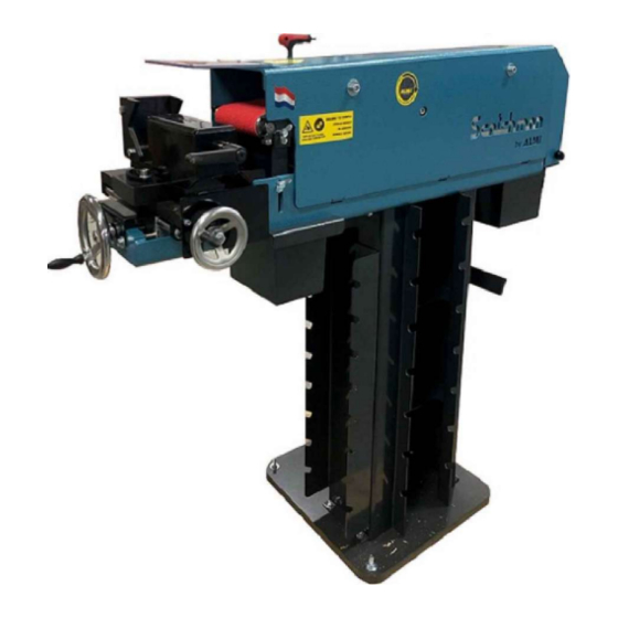
Summary of Contents for Scotchman AL150-HS
- Page 1 MODEL AL150-HS HIGH SPEED PIPE NOTCHER GRINDER VERSION 1 - JULY 2019 SCOTCHMAN INDS. - 180 E US HWY 14 - PO BOX 850 - PHILIP, SD 57567 Call: 1-605-859-2542...
- Page 2 MODEL AL150-HS HIGH SPEED PIPE NOTCHER GRINDER PAGE 2...
- Page 3 The AL150-HS is ideal for grinding & notching stainless steel and aluminum, producing a gap-free fit ready for welding. With the AL150-HS you are able to grind 3x faster than the AL150 due to the higher grinding belt speed of 4,300 RPM . Also, your...
-
Page 4: Table Of Contents
Drive for the Grinding Belt Securing a Tubing Section Angle Adjustment Depth Stop Length Stop Notching the Tubing Deburring NOTCHING CAPACITIES Angled Notching Capacity PAGE 4 SCOTCHMAN INDS. - 180 E US HWY 14 - PO BOX 850 - PHILIP, SD 57567 Call: 1-605-859-2542... - Page 5 10.0 AVAILABLE ROLLERS 11.0 AVAILABLE GRINDING BELTS 12.0 AL 150-HS PARTS LIST 12.1 AL 150-HS Exploded Views OPTIONAL BACK GAUGE PAGE 5 SCOTCHMAN INDS. - 180 E US HWY 14 - PO BOX 850 - PHILIP, SD 57567 Call: 1-605-859-2542...
-
Page 6: Introduction
The AL150-HS can feed the tube with either a handwheel or a lever. The pipe grinder/notchers offer trouble-free, accurate, quick and efficient machining of tubes and pipes for many years; and are backed by a 3-year warranty. -
Page 7: Warranty
2.1 WARRANTY Scotchman Industries, Inc. will, within three (3) years of the date of purchase, replace F.O.B. the factory or refund the purchase price for any goods which are defective in materials or workmanship, provided the buyer returns the warranty registration card within thirty (30) days of the purchase date and, at the seller’s option, returns the defective goods freight and delivery prepaid to the seller, which shall be the... -
Page 8: Machine Decals
3.0 MACHINE DECALS Qty Part # Description Item A050.00024 Safety Sticker 8 x 8 cm A050.00025 Sticker side flap 13x5 cm A050.00045 Instruction sticker AL150HS Triangle Pinch Point Sticker "CE" Identification on Other Side ALMI Motor Type AL 150 HS Volt Sr.No. -
Page 9: Warning Symbols
3.1 WARNING SYMBOLS BEFORE OPERATING THIS MACHINE PICTOGRAM 1: READ OWNERS MANUAL FIRST!! PICTOGRAM 2: USE OF EYE PROTECTION REQUIRED!! PICTOGRAM 3: USE OF HEARING PROTECTION REQUIRED!! PICTOGRAM 4: KEEP LID CLAP CLOSED WHILE BELT IS IN MOTION!! Strictly comply with all warning labels and decals on the machine. Never remove any of the labels and replace worn or damaged labels promptly!! PAGE 9... -
Page 10: Installation And Set Up
4.0 INSTALLATION AND SET UP ► CAUTION: THIS SECTION (4.0 to 5.0) DISCUSSES INSTALLATION AND SET-UP PROCEDURES. PLEASE READ THOROUGHLY BEFORE OPERATING THIS MACHINE. 4.1 PHYSICAL DIMENSIONS ► SEE FIGURE 2 ◄ DESCRIPTION INCHES ITEM Machine Height Length 134.6 78.7 Width 19-1/4 48.9... - Page 11 FIGURE 2 PAGE 11...
-
Page 12: Assembling Machine & Moving
4.2 ASSEMBLING MACHINE & MOVING ASSEMBLING OVERVIEW This grinder/notcher machine is shipped unassembled in a wooden crate. There are basically three (3) main parts. See FIGURE 3 on the next page. FOOT PLATE: This is a 1 inch thick by 19-1/2 inch square metal plate that sits on the floor. SUPPORT PILLAR: This is the rectangular "box"... - Page 13 Assembling Foot Plate, Pillar, Grinder and Waste Container MACHINE IS TOP HEAVY!! Use The Proper Lifting Equipment & Use Extreme Caution when moving GRINDER 4 BOLTS NUTS & WASHERS WASTE CONTAINER PILLAR WASTE CONTAINER 4 BOLTS & WASHERS FOOT FIGURE 3 PAGE 13...
- Page 14 Installing The HandWheels SMALL LARGE ALUMINUM ALUMINUM HAND-WHEEL HAND-WHEEL (side) (front) Installing The Feed Lever Below view is looking up at the front underside of the machine The larger (front) Feed Handwheel and Spindle must be removed (as shown) to use Feed Lever. Short Bolt Short Bushing Feed Lever...
-
Page 15: Machine Identification
4.3 MACHINE IDENTIFICATION These machines have a white "CE" Decal on them that Identifies the machine and has other important information such as machine Voltage, Hz, RPM, Weight & Year of Manufacture. This Decal is located on the black cover on the motor side of the machine, under the START & STOP buttons. -
Page 16: Wiring Diagrams
4.5 WIRING DIAGRAMS The wiring diagram for the AL 150 HS is on the next page - See FIGURE 6A. The wiring and electrical components are located on the motor side of the machine. To access the electrical components, a cover needs to be removed (shown below). The metal cover is mounted to the machine with six (6) bolts - Four (4) on the motor side and two (2) on the deburring end of the machine. - Page 17 EMER. COVER START INCOMING STOP SWITCH BUTTON LINE POWER BKWH ALMI 150 HS WIRING DIAGRAM 1 L1 3 L2 5 L3 1 L1 3 L2 5 L3 230V 460V 230V50/60Hz 230V50/60Hz Brown Brown Brown Black Black Blue Blue XTCE012B10 XTCE012B10 * Follow Instruction 2 T1 4 T2...
-
Page 18: Machine Start-Up
5.0 MACHINE START-UP This machine is equipped with (3) switches. The START and STOP buttons are located on the top of the machine. The 3rd switch is activated by opening or closing the hinged cover on the deburring end of the machine. REFER TO FIGURE 7 BELOW ON THE NEXT PAGE To start, push the Green START Button to start the machine. - Page 19 REAR COVER & SWITCH HINGED COVER COVER SWITCH PUSHER COVER SWITCH PLUNGER FIGURE 8 PAGE 19...
-
Page 20: Machine Controls & Adjustments
5.1 MACHINE CONTROLS & ADJUSTMENTS MODEL - AL150-HS REFER TO FIGURE 9 Allen key, 8mm, with handle; for securing rotatable tubing clamp, for securing standard stopper, and for adjustment of grinding belt. Allen bolts for opening and closing side cover. Use key with handle (1). - Page 21 MODEL - AL 150-HS CONTROLS & ADJUSTMENTS ITEM 7 DETAIL FIGURE 9 PAGE 21...
-
Page 22: Machine Operations
6.0 MACHINE OPERATION CAUTION: MAKE SURE ALL GUARDS AND COVERS ARE IN PLACE 6.1 STARTING AND STOPPING BELT The switches are located on top of the machine above the guard on the motor side of machine. To START the machine, push the GREEN button. To STOP the machine, push the RED button. -
Page 23: Depth Stop
6.5 DEPTH STOP Pipe Notcher is provided with a Depth Stop. There is a slot under the front of the machine and the Depth Stop is located there. The Depth Stop works to stop the movement of the support toward the grinding roller. This Stop is secured with an Allen bolt and the 8mm Allen key can be used for adjustment. -
Page 24: Length Stop
Again, a Length Stop is NOT included with the machine and can be fabricated by the user. NOTE: SCOTCHMAN INDS. HAS A OPTIONAL BACK GAUGE AVAILABLE FOR THIS MACHINE SEE PAGE 49 - P/N 04.00931... -
Page 25: Notching The Tubing
6.7 NOTCHING THE TUBING SEE FIGURE 9 After adjusting to the correct angle (7) and the Stops (if desired) have been set up, clamp a piece of tubing into the tubing clamp using the handle (6). The side with hand wheel (5) moves tubing clamp side to side. It must be positioned so the piece of tubing that is to be notched is moved toward the center of the grinding roller. - Page 26 TOOL REST IMAGES SEE FIGURE 12 Below TOOL REST MOUNTING SEE FIGURE 13 on the Next Page BOLT TOOL REST POSITION WHEN NOTCHING SLOT IN MACHINE & SHAFT ON TOOL REST FIGURE 12 PAGE 26...
- Page 27 TOOL REST IS 3/8" AWAY FROM GRINDING WHEEL - MOUNTING BOLT (below) IS TIGHT - READY FOR USE FIGURE 13 PAGE 27...
- Page 28 DEBURRING GUARD SEE FIGURE 14 BELOW If a large number of parts are being deburred, or if a grinding a large amount of material from a part is required, it is recommended that the extra deburring cover for the notching end of the machine is used. This cover is stored on the motor side of the machine below the motor and electrical cover.
-
Page 29: Notching Capacities
7.0 NOTCHING CAPACITIES SEE FIGURE 15 The capacity of the AL 150-HS machine is 1/2" to 4" O.D. (12.7mm to 114mm). Machine is supplied with (2) belts and (2) pipe mandrels (1-1/4" & 1-1/2"). There are 17 mandrels available to ensure correct gap-free fits. The grinding rollers (mandrels) and belt can be changed tool-free in seconds. -
Page 30: Angled Notching Capacity
7.1 ANGLED NOTCHING CAPACITY SEE FIGURE 16 Below shows the capacities for the AL 150 Grinder/Notchers when grinding tubes at an angle. The tube size must be reduced as the angle is increased. ANGLE RANGE: STRAIGHT=90° TO 20° 90° 60° 45° 30° 20° Max 1-7/8"... -
Page 31: Changing Rollers And Belt
8.0 CHANGING ROLLERS AND BELT SEE FIGURE 17 CAUTION: DISCONNECT POWER FROM MACHINE BEFORE PROCEEDING To gain access to the grinding belt, the large hinged side cover and hinged deburring cover must be opened. Use the Allen Key to turn the bolts indicated below to release the side cover. Note the the large hinged side cover is heavy and should be opened with care. -
Page 32: Notcher Roller Support
8.2 NOTCHER ROLLER SUPPORT SEE FIGURE 18 BELOW Before the grinding belt can be removed, the roller support on the notcher end of the machine must be loosened and one end of it disconnected. It is held in place by wing-nut type fasteners. -
Page 33: Changing The Roller
8.3 CHANGING THE ROLLER SEE FIGURE 19 BELOW After the grinding belt is removed, the roller can be changed. CAUTION: WEAR SAFETY GLOVES!! WITH INTENSIVE USE THE ROLLER CAN BECOME EXTREMELY HOT. Below are a couple of images that show how the roller mounts to the machine. Each roller has (2) bearings - One on each end. - Page 34 SEE FIGURE 20 BELOW Below is an exploded view of the roller and related parts. To remove roller, grasp roller and pull it out of the holder. Before the new grinding roller is installed, the recesses of the support for the grinding roller must be cleaned thoroughly!! NOTE: The bearings that are mounted on the grinding roller must be handled with care because they can be easily damaged.
-
Page 35: Setting Belt Tension
8.4 SETTING BELT TENSION SEE FIGURE 21 BELOW After changing the roller the belt can be installed. Slide the grinding belt over the drive pulley and the grinding roller. Make sure it is installed so it rotates in the right direction as shown in Sect. 8.1 NOTE: If a roller smaller than 30mm (1-3/16") diameter is being used, use a grinding belt that has been "broken in"... -
Page 36: Setting The Belt Tracking
8.5 SETTING BELT TRACKING After changing the roller and belt and tensioning it properly, The next thing is to check the tracking of the belt. You want the belt to run so it's as centered on the rollers as it can be. To begin, make sure the machine is still DISCONNECTED FROM POWER. -
Page 37: Adjustment Of Grinding Roller
8.6 ADJUSTMENT OF GRINDING ROLLER SEE FIGURE 23 The center of the grinding roller must be at the same height as the center of the tubing. This is set at the factory and generally doesn't need to be adjusted. If the center of the tubing isn't centered on the grinding roller it can be adjusted with the (2) bolts that are aligned vertically on the motor side of the machine - See Below. -
Page 38: Available Options
9.0 AVAILABLE OPTIONS 9.1 ROLLER HOLDER The AL150 HS Grinder Notcher has a place for (7) different sizes of notcher rollers to be stored on the side of the machine. If more storage is needed, we have a solution. There is a P/N 04.00303 - Roller Holder available for the AL150 HS Grinder Notcher. This holds (8) additional rollers allowing for storage of a total 15 rollers. - Page 39 ROLLER HOLDER INSTALLATION ENLARGED ISOMETRIC VIEW ROLLER HOLDER COLUMN EXTRA ROLLERS ARE STORED SECURELY IN CUT-OUTS FIGURE 25 PAGE 39...
-
Page 40: Available Rollers
10.0 AVAILABLE ROLLERS Below is a list of sizes and part numbers of the standard rollers we have for PIPE and TUBE. Intermediate sizes are also available. PIPE PART NUMBER TUBE PART NUMBER 1/2" A043.21.3 1.00" A043.26 3/4" A043.26.9 1.25" A043.32 1"... -
Page 41: Al 150-Hs Parts List
Strip 04.00881 Gear Conical M090.00002 Stamp Spring 25 / 12.5x38 M050.00001 Spring plunger GN615-M10-K 04.00875 Plate 04.00841 M010.00007 Handwheel DIN950-66-80-B10-F PAGE 41 SCOTCHMAN INDS. - 180 E US HWY 14 - PO BOX 850 - PHILIP, SD 57567 Call: 1-605-859-2542... - Page 42 Vlk.sluitr. M8 ev. Bzk.ck.schr. M10x190 07160.M10x190 01300.M10 Zk nut M10 07160.M6x20 Bzk.ck.schr. M6x20 07160.M6x10 Bzk.ck.schr. M6x10 07160.M6x35 Bzk.ck.schr. M6x35 07160.M4x20 Bzk.ck.schr. M4x20 PAGE 42 SCOTCHMAN INDS. - 180 E US HWY 14 - PO BOX 850 - PHILIP, SD 57567 Call: 1-605-859-2542...
- Page 43 Zk Nut M3 04.00175 Swivel Lever 04.00155 Guide Axis 04.00163 Threaded Spindle 04.00003 Slide Bearing 04.00004 Ring 04.00238 Cross Support PAGE 43 SCOTCHMAN INDS. - 180 E US HWY 14 - PO BOX 850 - PHILIP, SD 57567 Call: 1-605-859-2542...
- Page 44 A050.00025 Sticker Side Flap 13x5 cm 07840.M6x10 Bzk.st.schr. M6x10 45H ke. 04.00919 Switch (sam) 230V 50Hz A050.00045 Instruction Sticker AL150HS PAGE 44 SCOTCHMAN INDS. - 180 E US HWY 14 - PO BOX 850 - PHILIP, SD 57567 Call: 1-605-859-2542...
-
Page 45: Al 150-Hs Exploded Views
12.1 AL 150-HS EXPLODED VIEWS PAGE 45 SCOTCHMAN INDS. - 180 E US HWY 14 - PO BOX 850 - PHILIP, SD 57567 Call: 1-605-859-2542... - Page 46 MOTOR WITH MOUNTING PLATE & PULLEY PAGE 46 SCOTCHMAN INDS. - 180 E US HWY 14 - PO BOX 850 - PHILIP, SD 57567 Call: 1-605-859-2542...
- Page 47 PAGE 47 SCOTCHMAN INDS. - 180 E US HWY 14 - PO BOX 850 - PHILIP, SD 57567 Call: 1-605-859-2542...
- Page 48 PAGE 48 SCOTCHMAN INDS. - 180 E US HWY 14 - PO BOX 850 - PHILIP, SD 57567 Call: 1-605-859-2542...
-
Page 49: Optional Back Gauge
OPTIONAL BACK GAUGE Scotchmans has Back Gauge available for our ALMI Grinder/Notcher machines. It mounts to the side of the tube clamp and is a real Time-Saver when you have many pieces of tubing that are the same length that need to be notched. Contact your Dealer or call us at 1-605-859-2542.
Need help?
Do you have a question about the AL150-HS and is the answer not in the manual?
Questions and answers