
Related Manuals for Bucher Hydraulics EVM-UIS-2600 Series

Summary of Contents for Bucher Hydraulics EVM-UIS-2600 Series
- Page 1 Operating Instruction Universal power amplifier for proportional valves Series EVM-UIS-2600… Referenz: 400-B-900007-EN-00 Stand: 08.2021 1/46...
- Page 2 Because the products are subject to continual improvement, we reserve the right to amend the product specifications contained in this catalogue. The original language and legal terminology of all Bucher Hydraulics documentation is exclusively German. Bucher Hydraulics cannot be held liable for any possible errors in translation.
-
Page 3: Table Of Contents
CONTENTS General information ......................5 Order Number ........................ 5 Alternative products ......................5 Scope of supply ......................5 Accessories ........................5 Safety instructions ......................6 Characteristics ........................7 Function modes ......................7 Features ......................... 7 Device description ......................8 Use and application ......................9 Installation instruction ..................... - Page 4 4.5.5 Typical wiring ......................22 4.5.6 Parameter list ......................23 Examples for Input connections ................... 24 Technical data ......................25 Parameterdescription ....................... 26 FUNCTION (Function mode) ..................26 LG (Changing the language for the help texts) ............. 27 MODE (Switching between parameter groups) ............27 SENS (Failure monitoring)....................
-
Page 5: General Information
General information Order Number EVM-UIS-2600-2-30D-A1 Universal power amplifier with USB-interface for proportional valves Alternative products EVM-UIH-2600-2-30D-A1 Universal power amplifier for proportional valves EVM-ETC-2600-2-30D-A1 Universal power amplifier with EtherCAT-interface for proportional valves Scope of supply The scope of supply includes the module plus the terminal blocks which are a part of the housing. -
Page 6: Safety Instructions
Safety instructions Please read this document and the safety instructions carefully. This document will help to define the product area of application and to put it into operation. Additional documents and knowledge of the application should be taken into account or be available. General regulations and laws (depending on the country: e.g. -
Page 7: Characteristics
Characteristics This module is used for the control of one directional valve with two solenoids or one/two independent pressure or throttle valves with one solenoid each. Various adjustable parameters allow for an optimized adaptation to the respective valve. The integrated power amplifier with a short cycle time of 125 µs for the current loop is an inexpensive and space-saving solution. -
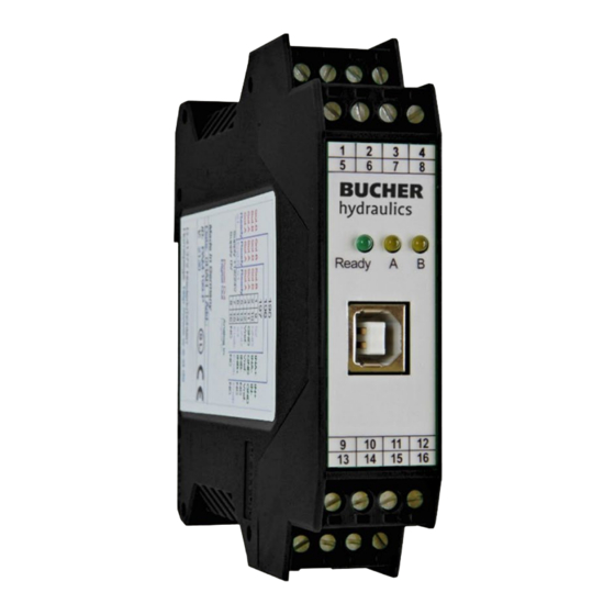
Page 8: Device Description
Device description Referenz: 400-B-900007-EN-00 Stand: 08.2021 8/46... -
Page 9: Use And Application
Use and application Installation instruction • This module is designed for installation in a shielded EMC housing (control cabinet). All cables which lead outside must be screened; complete screening is required. It is also a requirement that no strong electro-magnetic interference sources are installed nearby when using our open and closed loop control modules. -
Page 10: Commissioning
Commissioning Step Task Install the device in accordance with the circuit diagram. Ensure it is wired correctly and that the signals are well shielded. The device Installation must be installed in a protective housing (control cabinet or similar). Ensure that no unwanted movement is possible in the drive (e.g. switch off the hydraulics). -
Page 11: Function Modes And Technical Description
Function modes and technical description General information The EVM-UIH-2600-2-30D-A1 has three different function modes on his disposal. The functionality can be chosen by the command FUNCTION (195, 196 or 197). After this selection the settings have to be saved before the module may be loaded with a previously saved parameter set. -
Page 12: Control Of Directional Valves (Function 195)
Control of directional valves (Function 195) 4.3.1 Typical system structure This system consists of the following components: 1. Interface to PLC with analog and digital signals 2. Power amplifier EVM-UIS-2600-2-30D-A1 3. Proportional valve 4. Hydraulic cylinder 4.3.2 Method of operation This power amplifier is controlled by an analogue signal (from the PLC, from a joystick or a potentiometer). -
Page 13: Input And Output Signals
4.3.3 Input and output signals Connection Supply PIN 7 Power supply (see technical data) PIN 8 0 V (GND) Power supply (ground). Connection Reference voltages output PIN 12 Reference output voltage (8 V). Connection PWM output PIN 3 / 4 Current controlled PWM outputs for solenoid A. -
Page 14: Block Diagram
4.3.4 Block diagram 4.3.5 Typical wiring Referenz: 400-B-900007-EN-00 Stand: 08.2021 14/46... -
Page 15: Parameter List
4.3.6 Parameter list Command Default Unit Description FUNCTION Defining functionality Changing language help texts MODE Parameter mode (standard or expert) Activation and deactivation of the monitoring SENS AUTO functions Activation and deactivation of the CCMODE characteristic linearization PIN 5 Switching function of PIN 5 PIN 6 USCALE Switching function of PIN 6... -
Page 16: Control Of Two Throttle Or Pressure Valves (Function 196)
Command Default Unit Description Automatic adjustment of PPWM and IPWM parameters PPWM Control parameter for the current control loop IPWM Control of two throttle or pressure valves (Function 196) 4.4.1 Typical system structure This system consists of the following components: 1. -
Page 17: Input And Output Signals
4.4.3 Input and output signals Connection Supply PIN 7 Power supply (see technical data) PIN 8 0 V (GND) Power supply (ground). Connection Reference voltages output PIN 12 Reference output voltage (8 V) Connection PWM output PIN 3 / 4 Current controlled PWM outputs for solenoid A PIN 1 / 2 Current controlled PWM outputs for solenoid B... -
Page 18: Block Diagram
4.4.4 Block diagram 4.4.5 Typical wiring Referenz: 400-B-900007-EN-00 Stand: 08.2021 18/46... -
Page 19: Parameter List
4.4.6 Parameter list Command Default Unit Description Defining functionality FUNCTION Changing language help texts Parameter mode (standard or expert) MODE Activation and deactivation of the SENS AUTO monitoring functions Activation and deactivation of the CCMODE characteristic linearization OFF = Enable for both channels via PIN 15 ENABLE_B Range of the input signal monitoring (e. -
Page 20: Control Of Proportional Valves By Preprogrammed Values And Ramp Times (Function 197)
Command Default Unit Description PWM:A 2604 PWM frequency PWM:B 2604 Automatic adjustment of PPWM and IPWM parameters PPWM:A PPWM:B Parameters for the closed loop current controllers IPWM:A IPWM:B Control of proportional valves by preprogrammed values and ramp times (Function 197) 4.5.1 Typical system structure This system consists of the following components... -
Page 21: Input And Output Signals
In case of a fault, the power output stage will be deactivated and the fault will be indicated through a deactivated READY output and a flashing READY LED. To leave the error state the ENABLE has to be reset. The output current is closed loop controlled whereby a high accuracy and a good dynamic will be obtained. -
Page 22: Block Diagram
4.5.4 Block diagram 4.5.5 Typical wiring Referenz: 400-B-900007-EN-00 Stand: 08.2021 22/46... -
Page 23: Parameter List
4.5.6 Parameter list Command Default Unit Description Defining functionality FUNCTION Changing language help texts Parameter mode (standard or expert) MODE Activation and deactivation of the SENS AUTO monitoring functions Switching function of PIN 5 PIN 5 Switchover between one and two SOLENOIDS solenoids Ramp function... -
Page 24: Examples For Input Connections
Examples for Input connections Referenz: 400-B-900007-EN-00 Stand: 08.2021 24/46... -
Page 25: Technical Data
Technical data Supply voltage (Ub) [VDC] 12… 30 (incl. ripple) Current consumption w/o solenoid [mA] < 30 External protection 3 medium time lag Reference output Voltage Max. load [mA] Digital inputs < 2 > 10 Input resistance [kOhm] Digital outputs <... -
Page 26: Parameterdescription
Connections Communication USB type B Plug connectors 4 x 4-pole terminal blocks via the DIN mounting rail EN 61000-6-2: 8/2005 EN 61000-6-4: 6/2007 + A1:2011 Parameter description FUNCTION (Function mode) Command Parameter Unit Group FUNCTION FUNCTION x= 195|196|197 The general function of the module will be defined by this command. Functionality for directional valves with two solenoids and analogue input signals Functionality for two pressure/throttle valves with analogue input signals Functionality for directional, pressure and throttle valves with pre-programmed... -
Page 27: Lg (Changing The Language For The Help Texts)
5.2 LG (Changing the language for the help texts) Command Parameter Unit Group Function x= DE | EN Either German or English can be selected for the help texts in the PS1 software. After changing the language settings the parameter list has to be updated by pressing the speed button “ID”... -
Page 28: Ccmode (Activation Of The Characteristic Linearization)
Normally the monitoring functions are always active because otherwise no errors are detectable via the READY output. Deactivating is possible especially for troubleshooting. AUTO MODE: The module checks each second the actual failure status, which will (in case of a persistent error) trigger the LED and the READY output for a short time. -
Page 29: Pin 6 (Choice Of The Additional Function Of S1/Pin 6)
5.8 PIN 6 (Choice of the additional function of S1/PIN 6) Command Parameter Unit Group Function PIN:6 x= USCALE | RAMP This parameter defines the functionality of digital input PIN 6: USCALE: PIN 6 = active, USCALE will not scale the output PIN 6 = inactive, the output may be scaled by the USCALE parameter. -
Page 30: Enable_B (Switching Of The Enable Function)
5.10 ENABLE_B (Switching of the ENABLE Function) Command Parameter Unit Group Function ENABLE_B x= ON | OFF The setting of this parameter activates independent enable signals for channel A and B. If set to OFF, digital input PIN 15 enables both output channels. If set to ON, digital input PIN 15 enables only channel A and digital input PIN 6 enables channel B. -
Page 31: Pol (Output Polarity)
5.12 POL (Output reversal) Command Parameter Unit Group Function i= A | B POL:I x= + | - x= + | - Valves with one solenoid: This command allows a switch over of the output signal direction (after the MIN-MAX function). Example: POL:A + Input signal 0…... -
Page 32: Ain (Analogue Input Scaling)
5.14 AIN (Analogue input scaling) Command Parameter Unit Group Function i= A | B a= -10000… 10000 AIN:I a b c x b= -10000… 10000 c= -10000… 10000 0.01 % x= V | C This command offers an individual scalable input. The following linear equation is used for the ����... - Page 33 Typical examples: FUNCTION = 195 Input signal Description AIN:I Voltages input: Usable -10… 10V -10… 10 V (20V) for a working range of -100… 100% (two solenoids). AIN:I 1000 1000 Voltages input: Usable -10… 10V AIN:I (20V) for a working range of -100… -5…...
-
Page 34: Aa / Ab (Ramp Function / Acceleration Time)
5.15 AA / AB (Ramp function / Acceleration time) Command Parameter Unit Group Function i= UP | DOWN AA:I x= 1… 120000 AB:I x= 1… 120000 Two quadrant ramp function. The first quadrant means the ramp up and the second quadrant means the ramp down time. The ramp time is related to 100 % signal step. -
Page 35: Rmode (Choosing Ramp Function)
5.17 RMODE (Choosing ramp function) Command Parameter Unit Group Function RMODE x= SD | 4Q This command allows the switching between a set point related ramp function (SD), which makes it possible to assign an individual ramp time for each command value, and a four quadrant ramp function (4Q) with set point independent ramp times for acceleration and deceleration in both directions. -
Page 36: Ra (Ramp Function / Acceleration Time)
5.19 RA (Ramp function / Acceleration time) Command Parameter Unit Group Function i= 0… 7 RA:I x= 1… 120000 Presetting of the ramp times. Functionality depends on command RMODE. RMODE = SD: In this mode every command value has its own ramp time. For example: if you choose set point S:1 also ramp time RA:1 is chosen. -
Page 37: Cc (Kennlinienliniarisierung)
( ���� − ����1 ) ∗ (����1 − ����0) ���� = + ����1 ( ����1 − ����0 ) The influence of the linearization can be estimated via the process data on the monitor or on the oscilloscope. For the input of the characteristics linearization, the PS1 provides a table and a graphic data input. -
Page 38: Min (Overlap Compensation) / Max (Output Scaling) / Trigger (Threshold Value Of Min)
The influence of the linearization can be estimated via the process data on the monitor or on the oscilloscope. For the input of the characteristics linearization, the PS1 provides a table and a graphic data input. The input signal is mapped on to the X-axis and the output signal is mapped on to the Y- axis. -
Page 39: Min (Overlap Compensation) / Max (Output Scaling) / Trigger (Threshold Value For Min)
If the MIN value is set too high, it influences the minimal velocity, which cannot be adjusted any longer. 5.23 MIN (Overlap compensation) / MAX (Output scaling) / TRIGGER (Threshold value for MIN) Command Parameter Unit Group Function i= A | B MIN:I x= 0…... -
Page 40: Current (Nominal Output Current)
If the MIN value is set too high, it influences the minimal velocity, which cannot be adjusted any longer. 5.24 CURRENT (Nominal output current) Command Parameter Unit Group Function i= A | B CURRENT:I x x= 500… 2600 CURRENT x x= 500…... -
Page 41: Pwm (Pwm Frequenz)
reduce the hysteresis. This function is defined by the amplitude and frequency. The DITHER frequency should not be confused with the PWM frequency. Different amplitudes or frequencies may be required depending on the respective valve. The dither amplitude is defined in % of the nominal current. The PPWM and IPWM parameters influence the effect of the dither setting. -
Page 42: Acc (Auto Adaptation Of The Closed Loop Current Controller)
5.27 ACC (Auto adaptation of the closed loop current controller) Command Parameter Unit Group Function x= ON | OFF Operation mode of the closed loop current control. In automatic mode PPWM and IPWM are calculated depending on the preset PWM-frequency. Manual adjustment 5.28 PPWM / IPWM (Solenoid current controller P gain and I-gain) Command... -
Page 43: Process Data (Monitoring)
5.29 PROCESS DATA (Monitoring) Command Description Unit Function Command value after input scaling Command value after linearization Command value to current controller Output current of solenoid A Output current of solenoid B Command Description Unit Function Command value after input scaling channel A Command value after linearization channel A Command value to current controller channel A Command value after input scaling channel B... -
Page 44: Appendix
Appendix Failure monitoring Following possible error sources are monitored continuously when SENS = ON / AUTO: Source Fault Characteristics Command signal PIN 9 / 10 or The power stage is deactivated. Command signal PIN 14 / 13, Out of range 4...20mA Command signal PIN 9 / 10 or Out of range... -
Page 45: Troubleshooting
Troubleshooting Initial situation is an operable status of the device and existing communication between the module and the PS1 software. Furthermore, the parameterization of the valve control has to be done with the assistance of the valve data sheets. The RC mode in monitor can be used to analyze faults. If using the RC (Remote Control) mode, all safety aspects have to be checked solidly. -
Page 46: History
History Revison Datum Kurzzeichen Bemerkung 30.08.2021 FT / MAK Initiale Version Referenz: 400-B-900007-EN-00 Stand: 08.2021 46/46...
Need help?
Do you have a question about the EVM-UIS-2600 Series and is the answer not in the manual?
Questions and answers