
Related Manuals for Trox LVC

Summary of Contents for Trox LVC
- Page 1 Installation and commissioning instructions GB/en Easy control component for VAV terminal units LVC • TVE • TVR • TVJ • TVT • TZ-/TA-Silenzio • TVZ • TVA Read the instructions prior to performing any task!
- Page 2 TROX GmbH Heinrich-Trox-Platz 47504 Neukirchen-Vluyn, Germany Germany Telephone: +49 (0) 2845 202-0 Fax: +49 (0) 2845 202-265 E-mail: trox@trox.de Internet: www.trox.de A00000073971, 4, GB/en 02/2022 © TROX GmbH 2018 Easy control component for VAV terminal units...
- Page 3 Product data sheets Project-specific wiring documents, if any ENVIRONMENT! Environmental pollution hazard. TROX Technical Service To ensure that your request is processed as quickly as possible, please keep the following information ready: Tips and recommendations Product name ...
- Page 4 General information Safety notes as part of instructions Safety notes may refer to individual instructions. In this case, safety notes will be included in the instructions and hence facilitate following the instructions. The above listed signal words will be used. Example: Loosen the screw.
-
Page 5: Table Of Contents
2.2 Transport on site ........9 2.3 Bearing ............9 2.4 Packaging ..........9 Structure and functional description ... 10 3.1 Product overview types LVC, TVR, TVJ, TVT, TZ-Silenzio, TA-Silenzio, TVZ, TVA ..............10 3.2 Product overview TVE type ..... -
Page 6: Safety
They apply to the very location where The electronic control component type Easy is used in they are found. combination with a TROX air terminal unit for variable volume flow rate control in ventilation and air condi- WARNING! tioning systems. -
Page 7: Electric Shock Hazards
Safety Staff 1.3.1 Electric shock hazards In particular: The system owner must be aware of the applicable Electric current occupational health and safety regulations and carry out a risk assessment to determine any additional DANGER! hazards that may exist or result from the specific working conditions at the installation location. -
Page 8: Personal Protective Equipment
If any electronic components have been kept in an unheated area, condensation may form and damage TROX Technical Service the electronic components beyond repair. Staff of TROX Technical Service or of service partner companies approved and assigned by TROX GmbH. – Before you start commissioning, make sure that all devices have warmed up to the ambient tem- perature. -
Page 9: Transport, Storage And Packaging
Transport, storage and packaging Packaging Transport, storage and Moisture and lack of ventilation can lead to oxida- tion, even on galvanised components. Remove any packaging plastic wrapping in order to avoid oxidation. Protect the product from dust and contamination. ... -
Page 10: Structure And Functional Description
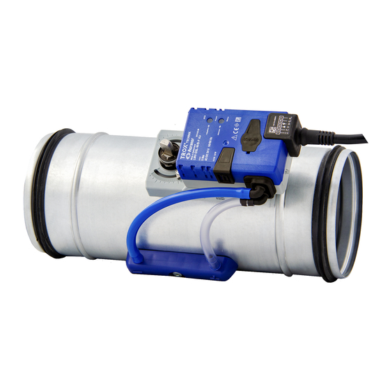
Structure and functional description Product overview types LVC, TVR, TVJ, TVT, TZ-Si... Structure and functional description 3.1 Product overview types LVC, TVR, TVJ, TVT, TZ-Silenzio, TA-Silenzio, TVZ, TVA Fig. 1: Easy controller mounted on the control unit e.g. TVR Easy controller... -
Page 11: Product Overview Tve Type
Structure and functional description Position of the damper blade 3.2 Product overview TVE type Fig. 2: TVE basic unit with Easy controller Easy controller potentiometer (V vmax Damper blade Test push button and LED to display the operating VAV terminal unit states, see table Lip seal Terminals... -
Page 12: Function Description
Clamping device (frictional connection) Basic function The Easy controller is an electronic control component for variable volume flow control for various TROX VAV terminal units. Its functional units consist of a dynamic differential pressure transducer, the controller elec- tronics and the actuator. -
Page 13: Operating Modes
Structure and functional description Operating modes > Operation with constant volume flow rate setpo... 3.5 Operating modes In regular operation, the integrated actuator is controlled by permanent evaluation of the offset (setpoint value- 3.5.1 Operation with constant volume flow actual) that adjusts the damper blade of the air terminal rate setpoint value unit via the axle mounting and thus regulates the volume flow rate to the setpoint value. -
Page 14: Operation With Variable Volume Flow Rate Setpoint Value
Structure and functional description Operating modes > Operation with variable volume flow rate setpo... 3.5.2 Operation with variable volume flow Operation with two setpoint values (min./max. switching) rate setpoint value Fig. 8: Min./max. switching Fig. 9: Variable volume flow control Volume flow rate setpoint value specification (q Volume flow rate limit specification (q and q... - Page 15 Structure and functional description Operating modes > Operation with variable volume flow rate setpo... Supply/extract air tracking control Fig. 10: Supply/extract air tracking control Volume flow rate limit specification (q and q Actual value volume flow rate as 0–10 V DC signal vmin vmax to the extract air controller...
-
Page 16: Characteristics
Structure and functional description Characteristics 3.6 Characteristics In order to specify a volume flow rate setpoint value to the Easy controller, a DC voltage signal in the range of Actual value signal 0–10 V DC must be applied to the terminal (w). The relationship between the nominal volume flow rate and the associated voltage signal can be calculated using the formula below. -
Page 17: Installation
Installation Installation Personnel: HVAC technician Protective equipment: Protective gloves Safety shoes Industrial safety helmet Only specialist personnel are allowed to perform the described work on the VAV terminal unit. Only skilled qualified electricians are allowed to work on the electrical system. -
Page 18: Wiring
Wiring Connection diagrams Wiring The control component contains no parts that can be replaced or repaired by the user and may only be Safety instructions opened by the manufacturer. Remove the transparent protective cap of the Easy controller only temporarily for wiring and commis- DANGER! sioning, not available for TVE. - Page 19 Wiring Connection diagrams Control constant volume flow rate q Switching between volume flow rates q and q vmin vmin vmax Fig. 14: Constant volume flow rate q vmin Fig. 16: Switching between volume flow rates q After applying the 24 V supply voltage, the controller vmin throttles the volume flow rate to the value set on the vmax...
- Page 20 Wiring Connection diagrams Override control on/off Fig. 18: Override control When using a 24 V AC supply voltage, special operating states, so-called override controls, can alternatively be activated. For this purpose, it is necessary to have a different cir- cuit with a diode circuit and volt-free switch contacts, provided by others.
-
Page 21: Commissioning And Operation
Commissioning and operation Setting of the control component Commissioning and operation 6.1 Setting of the control component Fig. 20: Setting the volume flow rate setpoint values, for example LMV-D3A potentiometer vmin potentiometer vmax The minimum or maximum volume flow rate is set via the potentiometer on the Easy controller. -
Page 22: Control Ranges Of Vav Terminal Units
Commissioning and operation Setting of the control component > Volume flow rate scale 6.1.1 Control ranges of VAV terminal units Each VAV terminal unit with Easy controller has a sticker with the volume flow rate scale. Note the individual volume flow rate and control ranges of the respective combination of the VAV terminal unit and the control component. -
Page 23: Setting Examples
Commissioning and operation Setting of the control component > Setting examples 6.1.3 Setting examples Example 1: TVR / 200 / Easy Nominal volume flow rate q of the control unit - 1459 m³/h vnom Required volume flow rate control range : 400 m³/h to q : 1000 m³/h vmin... -
Page 24: Default Settings Q
Commissioning and operation Setting of the control component > Setting variable volume flow control 6.1.4 Default settings q and q In the case of a variable volume flow control, the vari- vmin vmax able volume flow rate operating range is set via the potentiometers q and q , which is controlled via... -
Page 25: Functional Test
ð Logging actual value signal U 6.3 Switching the direction of rotation Personnel: TROX Technical Service Attention: only for service personnel – release by untrained personnel endangers the control function! Any volume flow rate deviations may be caused by an incorrect effect of direction of action (direction of rota- tion) of the controller. -
Page 26: Troubleshooting
The aim of volume flow control is to regulate the volume flow rate actual value to the specified setpoint value. If you cannot remedy a fault yourself, TROX Service will be happy to assist you with troubleshooting. Simply con- Sufficient output by the fan is therefore needed so that Ä... - Page 27 Troubleshooting Common faults > Deviation between setpoint value and actual va... If the potentiometer settings for q and q restrict vmin vmax the usable control range, this will change the character- istic curve of the setpoint signal. Since the actual value signal is always assigned to a characteristic curve of , a restriction of the usable control range results vnom...
-
Page 28: Systematic Troubleshooting
Troubleshooting Systematic troubleshooting 7.2 Systematic troubleshooting Start Störungsermittlung Störungsbehebung an VVS-Regelgeräten mit Easy-Regler Stand 24.4.2018 VVS-Regelgerät mit Easy-Regler Versorgungsspannung innerhalb der Toleranzangaben ? Nein Verdrahtung, Transformator prüfen Funktionsprüfung auslösen (Test-Taste drücken) Positionen Geschlossen, Offen, Regelposition werden automatisch nacheinander angefahren (dauert mehrere Minuten; Vorgang beobachten) Drehrichtung umprogrammieren Nein Nein... -
Page 29: Further Diagnostic Options
Klappenstellung? Regelposition nach Anlagendruck prüfen Offen Nein ca. 180 s ? Mindestdruckdifferenz eingehalten? (LED blinkt dauerhaft) Kanalabschnitt abgesperrt/Brandschutzklappe geschlossen? Geschlossen oder keine Veränderung (LED leuchtet dauerhaft) Troubleshooting Einstellung Einstellung Vmin/Vmax prüfen/korrigieren Vmin/Vmax Potentiometer Einstellung 0...100% oder zugelassen? Nein nutzbaren Regelbereich der VVS-Regelgeräte Serie beachten Further diagnostic options >... -
Page 30: Use Of Adjustment Devices
VAV terminal unit and the control component. Fig. 24: Adjustments sticker The information is required as part of the technical sup- port provided by the TROX service or for the ordering of replacement parts. 7.3.4 Ordering replacement controllers The device type and nominal width/dimensions are required to order an Easy replacement controller. -
Page 31: Disposal
Disposal Disposal After final decommissioning, the air terminal unit with the Easy type control component must be disposed of properly by a competent authority. The device contains electrical and electronic components and must not be disposed of as domestic waste. When disposed of, local up to date regulations must be complied with. -
Page 32: Technical Data
Technical data Technical data General operating conditions of the control components Ambient temperature 10–50 °C Ambient humidity 5-90% rF VAV terminal units Type Part number LMV-D3AL-F M466EU1 TROVE-024T-05I-DD15 A00000069228 LMV-D3A-F M466ES1 227V-024T-05-002 M466DC3 227V-024T-15-002 A00000053055 TVJ, TVT SMV-D3A M466ES3 TZ-Silenzio, TA-Silenzio, TVZ, TVA LMV-D3A M466ES2 1) Type TVJ all dimensions of type TVT up to and including dimension 1000x500... - Page 33 Technical data Easy controllers LMV-D3A and LMV-D3A-F 24 V AC ± 20%, 50/60 Hz Supply voltage 24 V DC −10/+20% Supply voltage 5 VA max. Power rating Max. 2.5 W Power rating Run time for 90° 110 – 150 s Setpoint value signal input 0 –...
- Page 34 Technical data Easy controller SMV-D3A 24 V AC ± 20%, 50/60 Hz Supply voltage 24 V DC −10/+20% Supply voltage 6 VA max. Power rating 3 W max. Power rating Run time for 90° 110 – 150 s Setpoint value signal input 0 –...
-
Page 35: Declaration Of Conformity
We hereby declare that the control component complies with all relevant provisions of the following EC guide- lines: Richtlinie 2014/30/EU Richtlinie 2014/35/EU Richtlinie 2011/65/EU The individual CE certificates can be found at www.trox.de . Easy control component for VAV terminal units... - Page 36 Germany TROX GmbH +49 (0) 2845 202-0 Heinrich-Trox-Platz +49 (0) 2845 202-265 47504 Neukirchen-Vluyn, Ger- E-mail: trox@trox.de many www.trox.de © TROX GmbH 2018...
Need help?
Do you have a question about the LVC and is the answer not in the manual?
Questions and answers