Table of Contents
Advertisement
Quick Links
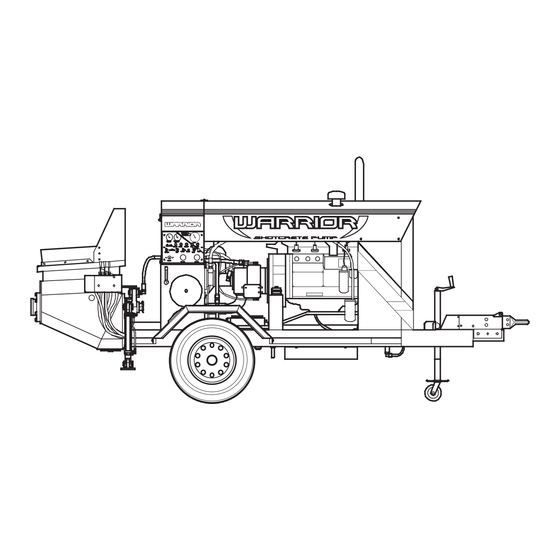
Model 3050
Owner's Manual
Look Inside For:
• Solving Problems
• Parts Lists
• Technical Schematics
WARRIOR
W
EST E R N
E
QUI P M ENT
� � � � � � � � �
� � � � � � � � � � �
� � � � � � � �
� � � � � � � �
� � � �
� � � �
� � � �
� � � � � �
� � � � � �
� � � � � � � �
� � �
� � �
� � � � � � �
� � �
� � � � � � � �
� � � � � �
� � � �
� � �
� � �
� � � � �
� � �
� � �
� �
� � � �
� �
� �
� � �
� � � �
� � �
2 0
� � �
� � � � �
� � � � � �
� � � � � � �
� � � � � � �
� � � � �
� � � � � � � �
� � � �
� � � � � �
� � � � � �
� � � � � � � �
� � � � � � � �
� � � �
Shotcrete Pump
™
Western Shotcrete Equipment, Inc.
™
www.wse-shotcrete.com
Toll Free: 1-887-592-7746
Advertisement
Table of Contents

Summary of Contents for WSE WARRIOR 3050
- Page 1 � � � � � � � � � � � � � � � � � � � � � � � � � � � � � � � � www.wse-shotcrete.com Toll Free: 1-887-592-7746 Western Shotcrete Equipment, Inc.
- Page 2 Western Shotcrete Equipment, Inc. Warrior Model 3050 Operation, Maintenance, and Safety Manual The following individual, who has signed below, hereby acknowledges receipt of this manual on behalf of the purchaser of the shotcrete pump. Machine Serial No. Sold To: Manual Received by: Name: Title: Signature:...
- Page 3 NOTICE THIS MANUAL IS IMPORTANT! This is the operation and maintenance manual for your shotcrete pump. It contains information necessary for safe and proper operation of the pump. All personnel who operate the pump must read and understand this manual. Call Western Shotcrete Equipment, Inc. toll free if you have and questions. (877-592-7746) This manual should be kept near the pump at all times.
- Page 4 WARRANTY ������� ��������� ���������� ���� �������� ���� ��� ��������� ���� ���� �� �� �� �� ���� ���� ������� �� �������� ��� ����������� ����� ������ ��� ��� ������� ��� � ������ �� ������ ���� ������ ���� ��� ���� �� �������� �� ��� ����� ������ ���������� �������...
-
Page 5: Table Of Contents
Table of Contents GENERAL INFORMATION ................................7 1 Foreword ..........................................7 2 Safety .............................................8 OPERATING INSTRUCTIONS ..............................9 1 Operator Qualifications ................................9 Introduction ...........................................9 1.1 Qualifications ..........................................9 2 Operating Principle ..................................10 3 Controls ..........................................11 3.1 Control Panel Diagram & Outrigger Controls ............................11 3.2 Machine Controls- Control Panel ................................12 3.3 Machine Controls- Hopper ....................................13 3.4 Hydraulic Fluid Level and Temperature Gauge ..........................13 4 Procedures... - Page 6 HYDRAULIC SYSTEM ..................................25 1 General/ Safety .....................................25 1.1 Hydraulic Fluid Precautionary Measures .............................25 1.2 Hydraulic Fluid First Aid ....................................25 1.3 Hydraulic Fluid Fire ......................................25 1.4 Hydraulic Schematic .......................................26 1.5 Operation ..........................................27 2 Components ......................................29 2.1 Control Components Diagram ..................................29 2.2 Valves ............................................30 2.3 Cylinders ..........................................31 2.4 Accumulator .........................................31 2.4b Accumulator Diagram &...
-
Page 7: General Information
GENERAL INFORMATION 1 Foreword Dear Customer, Thank you for your purchase of our Warrior Shotcrete Pump. By Selecting this machine, you have place your- self in a distinguished family of shotcrete/ concrete pump owners and operators. If you have any suggestions on how we could provide better products or services, please let us know by calling us toll free at 1-877-5-WARRIOR. -
Page 8: Safety
2 Safety Warning Do not attempt to operate this equipment without a thorough understanding of the operating, mainte- nance, and safety considerations contained in this manual. To prevent damage to equipment and or injury to you or other personnel, these instructions must be carefully followed. Warning Diesel is extremely flammable and is explosive under certain conditions. -
Page 9: Operating Instructions
OPERATING INSTRUCTIONS 1 Operator Qualifications Introduction Western Shotcrete Equipment, Inc. Warrior Shotcrete Pumps are high-pressure hydraulically powered piston pumps for shotcreting or pumping of concrete. This manual describes the operation, maintenance, and safety considerations that must be followed. Close attention to these details by the operator and mainte- nance personnel are necessary to ensure a minimum of problems while striving for maximum productivity and safety. -
Page 10: Operating Principle
2 Operating Principle The Warrior Shotcrete Pump consists of a receiving hopper, two material cylinders and pistons, and a swingtube valve. A continuous flow of concrete through the delivery line is produced by the sequence of op- eration of the two concrete pistons with the swingtube valve. The swingtube shifts between the two material cylinders under a controlled Electro/Hydraulic sequence to direct the flow between the two material cylin- ders, the hopper, and the discharge outlet. -
Page 11: Controls
3 Controls 3.1 Control Panel Diagram & Outrigger Controls � � � � � � � �� � ��� � � � � � �� � � � � � � � � � � � � � � � � �... -
Page 12: Machine Controls- Control Panel
3.2 Machine Controls - Control Panel 1) The IGNITION Switch has two positions: OFF and ON. On allows the engine to start. Off shuts off the fuel to the engine. 2) The START Button Engages the starter motor. Note: To avoid premature starter wear, do not operate the starter motor for more than 4 seconds at a time. Allow the starter motor to rest 10 seconds between starting attempts. -
Page 13: Machine Controls- Hopper
16) COOLANT LOW Light illuminates when the engine Coolant Level falls below the normal operating range. (Applies to water-cooled engines only. On air-cooled engines this light is renamed “V-Belt Failure” and will illuminate if the engine cooling fan drive belt breaks) 17) HYDRAULIC FLUID Light illuminates when the hydraulic fluid temperature exceeds the normal operating range. -
Page 14: Start Up
4.2 Start up An important part of pumping is the proper lubrication of the pipeline and/or hose system at the start of the pour. More downtime has been caused by inattention to this detail than any other reason. First, the hopper must be wetted. Then a rich, sloppy grout must be introduced to the hopper and slowly pumped into the pipeline system. -
Page 15: Clearing A Dry Pack
4.3 Clearing a Dry Pack When a block or dry-pack occurs in the delivery system, the pumping pressure gauge will reach the maxi- mum 3800-psi. Immediately switch the pump off. Switch the swingtube from forward to reverse, pump at least two or more strokes in reverse to relieve the pressure from the dry-pack back to the concrete pump. Shut the pump off. - Page 16 8) Clean the hopper out using a stiff brush and water. Warning THE OPERATOR SHALL NEVER PUT HIS OR HER HANDS IN THE CYLINDERS! 9) Start the engine and turn the pump on. Cycle a few times to make sure there is no material left in the cylinders.
-
Page 17: Maintenance
MAINTENANCE 1 Service Information Recommended engine oil: Shell Rotella T 15W-40 or comparable. Capacity: 4 gallons. Recommended hydraulic fluid: ISO-68, AW-68 (20W), Qualified against Denison HF-0. Meeting requirements of Vickers M-2950-S and 1-286-S specifications. Capacity: 55 gallons. Engine oil filter: Napa part #1820 Engine fuel filter: Napa part #3358 Engine air filter: Napa part #2l26 Hydraulic fluid filter element: Western Shotcrete Equipment part #83621... -
Page 18: Shotcrete Pump Module
SHOTCRETE PUMP MODULE 1 General 1.1 Pump Module Cross Section Western Shotcrete Equipment, Inc. -
Page 19: Remixer Assembly Cross Section
1.2 Remixer Assembly Cross Section Western Shotcrete Equipment, Inc. -
Page 20: Piston Cup Replacement Procedure
2 Piston Cup Replacement Procedure Warning Make sure your workspace is well ventilated. Never run the engine in an enclosed space The exhaust con- tains poisonous carbon monoxide gas that may cause loss of consciousness and lead to death. Warning Extreme caution is needed when working in the hopper and waterbox. - Page 21 13 With a small pry-bar, remove cup. 14 Remove all tools and parts from the hopper and the water-box. 15 Make sure the pump is “off”, in “forward” and “pumping” mode. 16 Start engine and turn the pump on. When the S-tube shifts, toggle the pump mode switch to “Pressure Test”.
-
Page 22: Wear-Plate/Wear-Ring Replacement Procedure
3 Wear-Plate/Wear-Ring Replacement Procedure Warning Extreme caution is needed when working in the hopper and waterbox. Use lock-out tag-out procedures. Al- ways remove the ignition key and put it in your pocket or other secure place when working in the hopper and water-box. - Page 23 14 Thoroughly clean the outlet cavity on the back of the hopper. 15 Thoroughly clean the 5” outlet flange. 16 Use a chipping gun to remove concrete build-up around the Wear-plate. 17 Remove the four Wear-plate bolts. (85132) 18 Tighten the Wear-plate push-bolt (85134) until the Wear-plate pops free. The push-bolt is located on the front of the hopper, operator side, near one of the side Wear-plate bolts.
- Page 24 35 Examine the seals in the flange bearing assembly. (85160) If they are in good condition, proceed to step # 43. 36 Remove the flange bearing assembly by removing the four mounting bolts then tighten the two-push bolts evenly. 37 Remove the outer seal and the inner seal and discard. 38 Thoroughly clean the flange bearing assembly.
-
Page 25: Hydraulic System
HYDRAULIC SYSTEM 1 General/Safety 1.1 Hydraulic Fluid Precautionary Measures Avoid prolonged breathing of vapor, mist, or gas. Workers should wash exposed skin several times daily with soap and water. 1.2 Hydraulic Fluid First Aid Eye contact: Flush eyes with plenty of water for several minutes. Get medical attention if eye irritation per- sists. -
Page 26: Hydraulic Schematic
1.4 Hydraulic Schematic �� � � � ��� � � � � ����� ACCUMULATOR PRESS � �� �� � � ��� �� RIGHT MAIN SYSTEM OUTRIGGER PRESS LEFT LR- CONSTANTPOWER CONTROL HPC 1 OUTRIGGER IN=MOREENGINE HP REQUIERED D- PRESSURECUT-OFF, ACTS A S RELIEF IN= INCREASEDOUTPUT PRESSURE, SET @ 3800 psi S- STAND-BY PRESSURE,FA CTORY SET @... -
Page 27: Operation
1.5 Operation The Western Shotcrete Equipment Warrior Shotcrete Pump has two 6” id x 42 (85401) chrome plated con- crete pumping cylinders powered by the 4” x 39” hydraulic main drive cylinders. (83200 or 93200, Cyl. A & The main pump is an axial piston pump (L), which generates the main oil flow. Flow from this pump is di- rected through a flow control valve (B) then into the Cycle block. - Page 28 The accumulator (Q) charge is directed through the pilot operated directional valve (H) then into the swingtube- actuating cylinder. (R) The pilot operated directional Valve is controlled by pilot oil from the solenoid operated pilot control valve. (G) The solenoid operated pilot control valve is controlled by the PLC. The 2nd stage of the tandem gear pump (N) powers the Remixer motor (S) and/or the jack stands.
-
Page 29: Components
F LOW ER CART.- G CO NTROL MODE UNLOAD ER / VALVE RELIEF VALVE (O range) (Y ellow ) MANUFACTURER PART WSE PART DESCRIPTION PILO T CYCLE VALV E D SH0 85C 4M D0 12LD 83413 FLOW CO NTROL VALVE NFED-LHN 83311... -
Page 30: Valves
2.2 Valves Setting the main relief valve 83301 (Sun RPGC-FCN) •Loosen locking nut with a 9/16” wrench. •Turn adjuster all the way out. •Start engine, place in pressure test mode, turn pump on and observe main hydraulic pressure gauge. •Turn adjuster in until the pressure gauge stops climbing. (It should stop climbing when it reaches the pump setting at 3800 psi.) •Turn adjuster In an additional 1/2 turn and tighten locking nut. -
Page 31: Accumulator
2.4 Accumulator Warning Use dry nitrogen gas only to pressurize the accumulator bladder. NEVER use compressed air. The use of compressed air or any other unstable gas can cause a fire or explosion resulting in serious injury or death. An accumulator stores hydraulic pressure. This hydraulic pressure is potential energy since it can change to kinetic energy. -
Page 32: Hydraulic Fluid
2.5 Hydraulic Fluid Recommended hydraulic fluid: ISO-68, AW-68 (20W), Qualified against Denison HF-O, Meeting requirements of Vickers M-2950-S and I-286-S specifications. Capacity: 55 Gallons. 2.6 Oil Cooler Western Shotcrete Equipment, Inc. -
Page 33: Electrical System
ELECTRICAL SYSTEM 1 General/Safety Western Shotcrete Equipment, Inc. -
Page 34: Wiring Diagrams
2 Wiring Diagrams 2.4 Ladder Diagram for pumps with a Deutz BF4M 1013C Engine R ED BLAC K ALT ERNAT OR STARTER M O TOR R ED XR -1 R ED16 BLAC K START 25 AMP ER -2 X1 7 .2/1 R ED12 WH ITE16 WH ITE16... -
Page 35: Wiring Diagram For Pumps With A Deutz Bf4M 1013C Engine
2.5 Wiring Diagram for pumps with a Deutz BF4M 1013C Engine Legend Act. Hyd. Fluid Act. ST to ST to Charge Cyl. B Temp Switch Cyl. A Diode Accumulator 200° Connection Not Connected Frame Ground Tachometer White 26 White 26 Engine Speed Sensor Black 26... -
Page 36: Ladder Diagram For Pumps With A Deutz Bf6L 913 Engine
2.6 Ladder Diagram for pumps with a Deutz BF6L 913 Engine BLACK ALTERNATOR FUEL PULL COIL STARTER MOTOR START 25 AMP WHITE 16 ER-2 WHITE 16 DL-2 RED 12 KEY SWITCH START SIGNAL WHITE 20 RED 12 RED 12 ER-4 YELLOW 16 DL-4 HYDRAULIC FLUID... -
Page 37: Wiring Diagram For Pumps With A Deutz Bf6L 913 Engine
2.7 Wiring Diagram for pumps with a Deutz BF6L 913 Engine Wiring Diagram 131 for pumps with BF6L 913 Legend Hyd. F luid Act. ST to ST to Charge Act. Temp Switch Cyl. A Accumulator Diode Cyl. B 200° Connection Not Connected Frame Ground Tachometer... -
Page 38: Components
3 Components 3.1 Proximity Switches Start Tur nma chin e Ob ser ve prox Does it cycle? sens or on op posite sid e of cup ad ap ter Y es Replace Isth e sen sor Sensor light on? Finish Y es Ob ser ve PLC status Run = on , Pw r = on... -
Page 39: Engine
ENGINE 1 General/Safety 1.1 Diesel Fuel Safety Warning Diesel is extremely flammable and is explosive under certain conditions. Work in a well-ventilated area with the engine stopped. Do not smoke or allow flames or sparks in your working area or where diesel is stored. Warning If the engine must be running to perform maintenance, make sure your workspace is well ventilated. -
Page 40: Frame
FRAME Western Shotcrete Equipment, Inc. -
Page 41: Troubleshooting
TROUBLESHOOTING 1 Pumping Pump cylinders are making very short strokes and S-Tube is switching rapidly back and forth. Probable cause- Out of sync The pumping cylinders can become out of sync when idling a long period of time between trucks. Should the cylinders become out of sync simply put the machine in pressure test mode by setting the Pressure test switch to “Press Test”... - Page 42 � � � � � � � � � � � � � � � � � � � � � � � � � � � � � � � � � � � � � � � � � � �...
- Page 43 -124 -120 83311 NFED-LHN -126 -124 BU-123 BU-121 -120 83301 -020 -018 RPGC-FCN 83304 LOHC-XDN 83411 RVCA-LAN -908 -017 -017 -015 -014 83406 DSH091ND012LD-X 83723 CXFA-XAN 83410 -020 -018 -018 QCDB-LAN -017 -017 -015 M200- -908 -014 -013 01000 83413 DSH085C4MD012LD...
- Page 44 Part Number Description 80000 WARRIOR 3050 81000 FRAME GROUP 81001 BRACKET, Brake Actuator, Mating 81002 GUSSETT, Corner 81003 CROSS MEMBER, Front 81004 CROSS MEMBER, Mid 81005 CROSS MEMBER, Rear 81006 FRAME RAIL, RH 81007 FRAME RAIL, LH 81008 GUSSETT, Top...
- Page 45 Part Number Description 81047 GUARD, Brake Actuator, 4.5” 81048 Battery Box, Single 81049 BRACKET, Support, Jack-Stand 81050 SUB-FRAME, Rear Step 81051 Safety Chain Attachment Bracket 81052 Bracket,Hyd.,Cyl.,Support; Front, Drive Cylinders 81053 Corner Gussett 9” length 1/4” Sheetmetal 81100 AXLE, Complete, 6.0K, W/Hydro. Brakes 81101 AXEL, 6.0K, Beam Only 81102...
- Page 46 Part Number Description 82105 FILTER, Oil, 2qt, (1820) 82106 FILTER, Fuel, (3358) 82107 DEFLECTOR, Air 82108 Starter 82109 Water pump 82110 KIT, Gasket, Seal, Water-pump 82111 Thermostat for Deutz BF4M1013C 82112 KIT, Seal, Thermostat for Deutz BF4M1013C 82113 SOLONOID, KIT, SHUT-DOWN, BF6L913 ,DUETZ 82114 SOLONOID, KIT, SHUT-DOWN, F4L912,DUETTZ 82150...
- Page 47 Part Number Description 82304 PIPE, Exhaust, 3” 82305 CLAMP, Exhaust, 3” 82306 MUFFLER, 24” , 3” In, 3” Out 82307 MOUNT, Rear, Exhaust System 82308 MOUNT, Front, Exhaust System 82309 ELBOW, 3” 82311 STACK, 3” 82312 STACK, 3” , Chrome 82313 BLANKET, Insulation 82400...
- Page 48 Part Number Description 83211 EXPANDER, 4” 83212 SEAL, Soft, 4” 83213 RING, Piston, 4” OD Cast Iron 3/16” Width 83214 O-RING, -129 83215 O-RING, -342 83216 B’UP RING, -342 83217 Bushing, Bronze, Oil Impregnated 83218 O-Ring, -229 83219 CARTRIDGE, Gland 83220 KIT, Seal, Wiper 83221...
- Page 49 Part Number Description 83304 Valve, Logic, Cartridge, Sun 83305 Seal Kit, Valve Logic (VITON) 83306 SEAL KIT (LOHC-XDN) 83307 Block, Cycle 83308 Base Plate, Cycle Block 83309 Body, Sun To Fit CXFA-XAN 83310 Valve, Double Throttle Check 83311 Cartridge, Valve, Flow Control 83312 Cycle Block, Mk IV 83313...
- Page 50 Part Number Description 83600.2 Mounting Rail for, Tank, Hydraulic Fluid 83601 Tank, Hydraulic, Top 83602 Tank, Hydraulic, Bottom 83603 Baffle, Tank, Hydraulic 83604 Cover, Access, Hyd. Tank, 12” 83605 Cover, Gasket, 12’’ Gasket & Washer Kit 83606 BRACKET, Accumulator 83607 RISER, Weld-on 83608 TUBE, Riser, Hyd.
- Page 51 Part Number Description 83709 Cooler, Oil, Single, Fan 83710 Filter, Return, Immersed, Tank 83711 Cyl. S-Tube Rod Seal Kit 83712 Cyl. S-Tube Gland Kit 83713 Weld-On, SAE Boss, #10 83714 Weld-On, 3/4 Pipe 83715 Gauge, Hyd. 5000# 83716 U-JOINT, 1/2” 83718 PLATE, Cover, D03 83719...
- Page 52 Part Number Description 83751 PLUG, -16 SAE Hex plug (6408-16) 83770-019 CYLINDER, Outrigger, 2” x 12” CYLINDER 83752 ELBOW, 16FL5K-16MJ90 83770-018 CYLINDER, Outrigger- 6 SAE BOSS WELD-ON FITTING 83753 SPLIT-FLANGE, SFK-16 83770-017 CYLINDER, Outrigger MB-MJ 6-6 FITTING 83754 FITTING, MB12-MJ10 90 (6801-10-12) 83770-016 CYLINDER, Outrigger CYLINDER CAP 83755...
- Page 53 Part Number Description 83794 OIL COOLER FRONT MOUNTING KIT 83800 Hoses & Lines 83801 LINE, Bypass, Front, .625x90° 83802 HOSE, Valvoil In x P3 83803 HOSE, Valvoil out x Oil Cooler 83804 HOSE, Remixer 83805 HOSE, Jackstand, Top, RH 83806 HOSE, Jackstand, Bot, RH 83807 HOSE, Jackstand, Top, LH...
- Page 54 Part Number Description 83904 JEWEL GLAND, Cylinder, 2.5x5 Stroke, MkII 83905 KIT, Seal , Jewel Gland, Cylinder, 2.5x5 Stroke, MkIIKIT, Seal , Jewel Gland, Cylinder, 2.5x5 Stroke, MkII 83906 SHCS, 3/8-16x2.25 83907 ROD, Cylinder, 2.5x5 Stroke, MkII 83908 PISTON, Cylinder, 2.5x5 Stroke, MkII 83909 KIT, Ring, Piston, Cylinder, 2.5x5 Stroke, MkII 83910...
- Page 55 Part Number Description 84203 RELAY, Gen Purpose 84204 SOCKET, Relay, Gen Purpose 84205 RELAY, Timer, Off-Delay, TCR2 U12D 84206 SOCKET, Relay, Timer, Off-Delay 84207 FAN, Tubeaxial, DC, 12v, Cooling, PLC 84208 ENCLOSURE, Control, PLC 84209 CORD-GRIP, Nylon, 3/8” 84211 CORD-GRIP, Nylon, 3/4” 84212 CORD-GRIP, Nylon, 1/2”...
- Page 56 Part Number Description 84278 Adapter, SIGNAL CONVERTER, PNP-NPN SIGNAL 85000 PUMP GROUP 85100 Hopper, MkII 85101 Hopper, Front, Mk II 85102 Hopper, Rear, MkII 85103 Frame, Door, Hopper 85104 Guard, Splash, Hopper 85105 Cover, Hopper 85106 CORNER, Front, Hopper 85107 CORNER, Rear, Hopper 85108 PLATE, Bottom, Hopper...
- Page 57 Part Number Description 85161 BEARING, Flange, 3” ,MK III 85162 BEARING, Brass, 3” MK III 85163 SEAL, Outer, Shaft, S-Tube, for 3” shaft 85164 Seal, Lip, Inner, 3” , Flange Bearing 85165 HHCS, 1/2-13x2.5 Grd8 85166 Flange Bearing, MkIV 85170 KIT, Seal, Outlet 85171 HOUSING, Bearing, Outlet...
- Page 58 Part Number Description 85232 PIN, Threaded, 3/4-10 85233 BUSHING, Pin, Paddleshaft 85234 CLEVIS, Remixer Paddle-Shaft 85235 FITTING, HYDRAULIC MOTOR., MOR 10-MJ6 90 DEG. 85236 FITTING, HYDAULIC MOTOR. , MOR 10-MJ6 85300 SWINGTUBE, MKII 85301 SHAFT, Swing-Tube 85302 Droparm, Swingtube, 3” , 1-1/4” Thick 85303 Adapter, Tapered, Pipe, Swingtube 85304...
- Page 59 Part Number Description 85605 STIFFENING BAR, Waterbox, MkII 85606 SHCS, 3/4-10x2.25 85607 Half Coupling, Weld-on, 1 1/2 Pipe, 9/16” L 85608 PLUG, Pipe, 1 1/2 85609 WASHER, 3/4 85610 COVER ASSEMBLY, Waterbox 85611 FRAME, Cover, Waterbox 85612 WINDOW, Cover, Waterbox 85613 THUMBSCREW, 1/4-20 85614...
- Page 60 Part Number Description 86203 COVER, Engine, Right Side Panel 86204 COVER, Engine, Left Side Panel 86205 COVER, Engine, Top Door Frame 86206 COVER, Engine, Bottom Door Frame 86207 LATCH, Door, Engine Cover 86208 HINGE, Door, Engine Cover 86210 LOUVER, Engine Cover 86211 SHROUD, Cooler, Oil, Hydraulic 86212...
- Page 61 Part Number Description 87021 SAFETY DECAL, 2.5L X 5W 87022 SAFETY DECAL, 2.5L X 5W 87023 WARRIOR Bolt Large Side Decal, 55” X 9” Engine Cover Decal 87024 Model 3050 Stripe decal, 49” X 5” Front stripe decal 87025 18” X 2” FRONT WARRIOR DECAL 87026 SIDE WARRIOR DECAL 15”...
Need help?
Do you have a question about the WARRIOR 3050 and is the answer not in the manual?
Questions and answers