
Summary of Contents for Aura LM-270
- Page 1 Metal Cutting Band Saw Model LM-270 F o r y o u r s a f e t y , p l e a s e r e a d t h i s m a n u a l...
-
Page 2: Table Of Contents
CONTENT Specifications Clamping the work piece Safety Adjust cutting angle Safety Instructions For Power Tools Operation cycle Additional Safety Instructions For The Adjusting Metal-cutting Bandsaw Blade tension adjusting Site Considerations Adjusting the blade guide Getting to Know your Metal Cutting Blade guide block BandSaw Changing the blade... -
Page 3: Safety
13. DON’T OVERREACH. Keep proper footing and balance at SAFETY all times. 14. MAINTAIN TOOLS WITH CARE. Keep tools sharp and For Your Own Safety Read Instruction clean for best and safest performance. Follow instructions Manual Before Operating This Equipment for lubricating and changing accessories. -
Page 4: Site Considerations
Lighting and Outlets Like all power tools, there is danger associated with this Metal Bandsaw. Accidents are frequently caused by lack of Lighting should be bright enough to eliminate shadow familiarity or failure to pay attention. Use this tool with and prevent eye strain. -
Page 5: Bandsaw
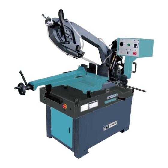
GETTING TO KNOW YOUR METAL CUTTING BAND SAW Saw arm lock lever Contorl panel----Contains On/Off buttons, Power- Vise hand -wheel On indicator light, and the Feed Rate valve. Vise quick lock lever Main motor Jaw, vise Sling plate Hydraulic cylinder Coolant and chip tray Saw arm Bar stop/ work stop... - Page 6 Gear box Fork, Auto/manual changing Saw arm return spring Hydraulic flow control valve Hydraulic flow regulation valve Stroke lower position limit switch...
-
Page 7: Unpacking
UNPACKING The metal bandsaw is shipped from the factory in a carefully packed crate. If you find the machine to be All die-cut metal parts have a sharp edge (called “flashing” damaged, save the containers and all packing materials, ) on them after they are formed. This is generally removed call your agent. -
Page 8: Assembly
ASSEMBLY Check the condition and suitability of the equipment This metal cutting bandsaw is completely assembled, just available. needs to assemble the machine stand. Do not touch the suspended loads and remain at a Assembling the machine stand safe distance from them. Join the left part, right part to bottom plate with 6-hex head screws M8x16 w/6- 8mm washers. -
Page 9: Operation
OPERATION The machine has been designed to cut metal building materials, with different shapes and profiles, used in workshops, turner’s shops and general mechanical structural work. Only one operator is needed to use the machine, that must stand on the front of machine as shown in the picture. -
Page 10: Adjust Cutting Angle
Fig 9 Fig 7 Adjust cutting angle Using the right side, angles can be cut up to 60 degrees. This requires that vise jaw to be set on the left side(6, fig6). Use the procedures for Vise Adjustment, to place it in left side position. Using the left side, angles can be cut up to 45 degrees. - Page 11 Fully open the hydraulic flow control valve(A) by turning the valve counter-clockwise all the way to the end. Press trigger switch(J) to start operation. If cutting pipe with thin walls, reduce the saw arm descent rate by adjusting the flow control valve(A). Press the emergency push button(K fig11,or SB1 fig8) down to shut off all functions.
-
Page 12: Adjusting
ADJUSTING Blade tension adjusting The ideal tension of the blade is achieved rotating the hand wheel until it touches the micro switch, that actuates the operation of the machine is actuated. The position of this switch is factory set during inspection, after having tightened the blade on the lengthening values indicated by its manufacturer as per specific dimensions set with... -
Page 13: Adjusting The Blade To The Flywheel
Checking the adjustment of the blade Use a strip of scrap paper and slide it between the blade and the flywheel while it is running. if the paper is cut then the blade is riding too close to the flange. Re-adjust. if you notice that the blade is riding away from the flange.Then re-adjust. -
Page 14: Maintenance
The gear box MAINTENANCE The maintenance jobs are listed below, divided into The gear box requires periodic changing of oil. The oil Daily, Weekly, Monthly and 6-monthly intervals. If the must be changed by the first 6 months of a new following operations are englected, the result will be machine and every year thereafter. -
Page 15: Blade Choice
BLADE CHOICE 4. In the applicable row, read across to the right and find the box where the row and column intersect. Listed in Selecting the right blade for the job depends on a variety the box is the minimum TPI recommended for the of factors, such as the type of material being cut, variable tooth pitch blades. - Page 16 Blade Structure COMBO TOOTH Pitch varies between teeth and consequently varying teeth size and varying gullet depths. Pitch varies between teeth, Bi-metal blade are the most commonly used. They consist of which ensures a smoother, quieter cut and longer blade life silicon-steel blade backing by a laser welded high speed steel owing to the lack of vibration.
-
Page 17: Electrical System
ELECTRICAL SYSTEM Main Switch SA1: Hi/Low Speed Control SA2: Mode Switch Contactor Thermal protector Transformer FU1-3: Fuse 8A FU4: Transformer Fuse 2A HL1: Power Light HL2: Run Light SB1: Emergency Stop Button SB2: ON Button SB3: Button on Grip-hand SQ1-3: Limit Switch... -
Page 18: Troubleshooting
TROUBLESHOOTING This chapter lists the probable faults and malfunctions that could occur while the machine is being used and suggests possible remedies for solving them. The first paragraph provides diagnosis for TOOL and CUTS, the second for ELECTRICAL COMPONENTS. FAULT PROBABLE CAUSE REMEDY Tooth Breakage... - Page 19 FAULT PROBABLE CAUSE REMEDY Premature Blade Wear Faulty running-in of blade See “Material classification and blade selection” in the Blade running –in section. Teeth positioned in the direction opposite Turn teeth in correct direction. the cutting direction Poor quality blade Use a superior quality blade.
- Page 20 FAULT PROBABLE CAUSE REMEDY Check distance between pads (see “Machine Blade guide pads not regulated or dirty because of lack of maintenance. adjustments” in the Blade Guide Blocks section): extremely accurate guiding may cause cracks and breakage of the tooth. Use extreme care when cleaning.
- Page 21 FAULT PROBABLE CAUSE REMEDY Irregular work of the blade due to the lack of Broken teeth. teeth can cause deflection in the cut; check blade and if necessary replace it. Check level of liquid in the tank. Increase the Insufficient lubricating refrigerant or flow of lubricating coolant, checking that the wrong emulsion.
- Page 22 FAULT PROBABLE CAUSE REMEDY “SA1” two speed switch It must be exactly turned towards Rabbit or The band rotation motor does not work. Turtle sign. Main motor over-load relay Push down FR1 red button. After a motor cooling time of 5 minutes, if there is no current continuity on these two wires, the motor must be replaced.
-
Page 23: Parts List & Diagram
DIAGRAM & PARTS LIST Description Size Q’ty Description Size Q’ty Base(Bottom Plate) 40-1 Bolt Guide 40-2 Spring Washer Base (Left Part) Set Screw M6x12 Washer Base (Right Part) Handle M8x25 Door frame Rooler Stand Hex.Cap Bolt M8x16 Hex.Cap Bolt M12x25 Washer Spring Washer Door... - Page 24 Description Size Q’ty Description Size Q’ty Setting Washer Star Washer Lock Lever Device Anti-Dust Cover Handle Ball Bearing 32008 Setting Plate Shaft Bushing Hex.Cap Bolt M10x45 Allen Screw M8x20 130-1 Spring Washer Pointer Electric Box Holder Allen Screw M5x8 Spring Washer Cover Allen Screw M8x20...
- Page 25 Description Size Q’ty Description Size Q’ty Hose 5/16"x40cm 1 Set Screw M6x12 Hose 5/16"x90cm 1 Allen Screw M8x20 Drive Flywheel Bracket Setting Washer Allen Screw M12x50 207-1 Spring Washer Handle Hex.Cap Bolt M10x25 Guide Bracket 209A Idle Flywheel Shaft Spacer,Guide Roller Bearing 32007 Washer...
- Page 26 Description Size Q’ty Description Size Q’ty 287-1 Bushing Konb Lead Screw Seat 307-1 Bushing Bearing Bushing Shaft 289-1 Ball Bearing 2035 289-2 C-Ring 289-3 Hollow Pin Φ6x35 Allen Screw M10x25 Trigger Switch Spring Washer Pipe Post 292-1 Set Screw M10x16 Hydraulic Cylinder Post Spring Hook Spring Washer...
Need help?
Do you have a question about the LM-270 and is the answer not in the manual?
Questions and answers