Table of Contents
Advertisement
Quick Links
Instruction Manual
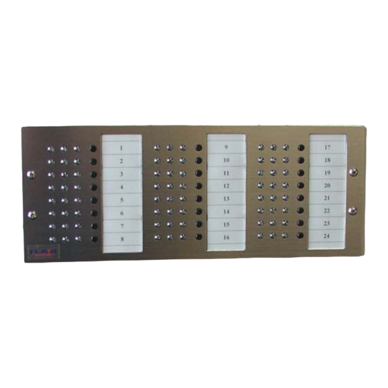
Multi‐Zone Annunciator
The 561A Multi-Zone Annunciator is ready to use from the factory. It
comes pre-configured with basic factory (default) settings and will work
with NC or NO devices with 1K Ohm EOL Resistors.
Model 561A
June 2012
Revision 2
Table of Contents
Features ........................................................................................ 2
General Specifications .................................................................. 3
System Overview .......................................................................... 4
1.
General ................................................................................. 4
2.
Typical Operation ................................................................. 4
3.
Detailed Operation ................................................................ 5
3.1.
Input Loop Types ............................................................. 5
3.1.1.
N.C./N.O.– 1000 Ohm EOL ......................................... 5
3.1.2.
N.C. – 1000 ohm EOL ................................................. 5
3.1.3.
N.O. – 1000 Ohm EOL ................................................ 5
3.1.4.
Fire – 1000 Ohm EOL .................................................. 5
3.1.5.
High Security – 2000 Ohm EOL .................................. 6
3.2.
Zone Input Configurations ................................................ 6
3.2.1.
24 Hour ........................................................................ 6
3.2.2.
Entry Delay .................................................................. 6
3.2.3.
Exit Delay ..................................................................... 6
3.2.4.
Prop Delay ................................................................... 7
3.3.
Digital Input Configuration ................................................ 7
3.3.1.
Acknowledge ................................................................ 7
3.3.2.
Reset ............................................................................ 7
3.3.3.
Shunt Disable w/ Memory ............................................ 7
3.3.4.
Shunt Disable............................................................... 7
3.3.5.
Master Shunt - Arm/Disarm ......................................... 8
3.3.6.
Lamp Test .................................................................... 8
3.4.
LED Operation ................................................................. 8
3.4.1.
Yellow LED – Shunt (Arm/Disarm) .............................. 8
3.4.2.
Green LED – Loop Status ............................................ 8
3.4.3.
Red LED - Alarm .......................................................... 9
3.5.
Common Output Types .................................................... 9
3.5.1.
Non-Latch .................................................................... 9
3.5.2.
Latched ........................................................................ 9
3.5.3.
Pulsed .......................................................................... 9
3.5.4.
Timed ........................................................................... 9
3.5.5.
Audible ....................................................................... 10
3.5.6.
System Arm ............................................................... 10
3.6.
Individual Output Types ................................................. 10
3.6.1.
Non-Latch .................................................................. 10
Advertisement
Table of Contents

Summary of Contents for Flair Super Nurse Call 561A
- Page 1 Table of Contents Features ..................2 General Specifications ..............3 System Overview ................4 Instruction Manual General ................. 4 Typical Operation ..............4 Multi‐Zone Annunciator Detailed Operation ..............5 3.1. Input Loop Types ............. 5 Model 561A 3.1.1. N.C./N.O.– 1000 Ohm EOL ......... 5 3.1.2.
-
Page 2: Table Of Contents
Annunciator-Controls or in combination with any Control Panel. Bench Testing ..............13 Programming ..............15 This Manual describes the basic installation and operation of the Flair Multi-Zone Annunciator. There are several configurations with up to 40 7.1. Install Configuration Software ........15 Options to customize your Annunciator. - Page 3 System Overview General Specifications 1. General Mounting Configuration The 561A Multi-Zone Annunciator is ready to use from the factory. 561A - Recessed w/ Power Supply in separate enclosure It comes Pre-Configured with basic Factory (Default) settings of Power Requirements Eight Burglar Zones.
- Page 4 Zone Push Button – The Zone Push Button provides for individual 3.1.5. High Security – 2000 Ohm EOL Zone Control of Acknowledge, Reset and Shunt (Arm/Disarm). Secure – 1.5-2.5K Ohms Momentarily pressing the Zone Pushbutton will: Door open alarm – 4.5-6K Ohms Acknowledge a Zone in Alarm Magnetic tamper alarm –...
- Page 5 3.2.4. Prop Delay When this input is activated, grounded low: All Zones will become Armed. Provides a programmable Delay Period to pass thru a All Yellow LEDs will turn OFF. Zone and cause no Alarm Output. The Arm/Disarm feature of the Zone Pushbuttons will be When the Zone is Disarmed there will be a disabled.
-
Page 6: Latched
Turn off while the input is in an Alarm condition. 3.5.5. Audible Return to a steady on after an Alarm condition is restored Output will Pulse during Exit/Entry Delays. to a secure condition. Output will activate upon Alarm. Flash while the input is in a Trouble condition @ 2cps Output will reset when the Zone is acknowledged. -
Page 7: Input To Output Mapping
4.1. Table 4-1 3.7. Input to Output Mapping Zone Input / Output Configuration The Annunciator Module has 8 inputs and 8 individual outputs per 8 Zone Module. They are Factory configured to operate on a 1 to 1 Zone Loop Entry Exit Prop... -
Page 8: Planning The System
Using the free end, connect the 12Vdc Input Harness to a 12Vdc power source. Connect the 12Vdc Input Harness to J8 – 2 pin header, on the The speed and efficiency of installing a Flair Annunciator will be Termination Module. greatly enhanced by planning the installation. Programming can be... -
Page 9: Programming
Configuration Software. This requires a PC (Desktop or Laptop) Select all files and copy to a blank CD. with a RS232 Serial Port and a Flair RS232 Adapter (NOTE: A USB to Insert the newly copied CD into the computer auto-... -
Page 10: Begin Programming
Using the copy of the PROGRAMMING GUIDE, (Appendix B), that COM 1. you completed during the “Planning of the System”, Section 5, make changes to the configuration on the Flair Configurator The box in the lower left corner of the Configurator menu, below Software. -
Page 11: Zone Wiring - J1 Connector
Attach an earth ground wire to box. Use a minimum 14 gauge wire and connect this wire to a ground stake. Do not use a conduit, gas pipe, or water pipe for a ground reference. CAUTION: DO NOT Appling power to the Annunciator Earth ground the negative side of the power supply, as this will Once all field wiring has been completed and checked for opens, greatly reduce lightning/transient protection. -
Page 12: Or Fire - 1000 Ohm Eol
Separate Source to the common ground of the Ohms, and a Normal Alarm Loop resistance of 5300 Ohms. Annunciator Power Source. Flair Electronics manufactures 2-Wire Balanced Magnetic Contacts in this configuration. 8.5. Power Input – J8 Connector If Annunciator is provided with a DC Power Supply, connect the Red (+13.8Vdc) and Black (Ground) wires of connector J8 to the (+) and... -
Page 13: Wire Lead Color Code And Description
8.6. 8.7. Wire Lead Color Code and Description Annunciator Termination Module Descriptions J1 – Zone Inputs J2 – Digital Inputs J3 – Individual Outputs Color Description Pin Description Color Description Black Common - Black Common - Brown Output 1 Brown Zone 1 Brown Input 1... -
Page 14: Appendixes
Opt 10 – 110VAC Transformer Built-in – Provides a Built-in Transformer Collector Outputs for any Annunciator that comes standard with a Plug-in-the-wall NOTE: The following is a complete list of the Options available on Flair Transformer. Annunciators. Not all Options or combinations of Options are available Opt 11 –... - Page 15 Input is faulted and will deactivate only after the Input is restored the Bypass Toggle Switches, Silence Switch or Reset Switch. With and reset. the Keyswitch ON, the Annunciator will be Disarmed, The Annunciator will not respond to any Alarm Condition. Opt17A –...
-
Page 16: B - Programming Chart
Opt 33A – Circuit Test – (200 Series Annunciators Only) Provides a Push Button to cause all Zones to Alarm. Programming Chart Opt 34 – Individual Reset – (200 Series Annunciator Only) Provides an Individual Reset button for each Zone. (Standard on 500 Series Annunciators) Opt 34A –... -
Page 17: C - Diagrams
9.3. C – Diagrams Digital Input Type Digital Input Input # Type Black (Common) Common Output Type Output Output Type Output Time (Min) Input Bridging to Zone Outputs Output Input 1 Input 2 Input 3 Input 4 Input 5 Input 6 Input 7 Input 8... -
Page 18: D - Warranty
There is absolutely no warranty on software and all software products are damages. If the laws of such a jurisdiction apply to any claim by or against Flair sold as a user license under the terms of the software license agreement included with the Electronics, the limitations and disclaimers contained here shall be to the greatest extent product. -
Page 19: E - Fcc Compliance Statement
E - FCC Compliance Statement FLAIR ELECTRONICS, INC. END USER LICENSE AGREEMENT FLAIR CONFIGURATOR This License Agreement, made between Flair Electronics, Inc., a corporation of the CAUTION: Changes or modifications not expressly approved by Flair Electronics State of California hereinafter referred to as LICENSOR, and the acknowledged could void your authority to use this equipment. - Page 20 THIS AGREEMENT. IF LICENSEE DOES NOT AGREE TO ALL OF THE TERMS Flair Electronics OF THIS AGREEMENT, CLICK THEN DO NOT INSTALL THE SOFTWARE. Copyright 2006, Flair Electronics, Inc. 800 Palomares Ave, La Verne, California, 91750. 212 Mercury Circle Pomona, CA 91768...
Need help?
Do you have a question about the Super Nurse Call 561A and is the answer not in the manual?
Questions and answers