Table of Contents
Advertisement
Available languages
Available languages
Quick Links
INSTRUCTIONS MANUAL
J
.P. SELECTA s.a.u.
CODE 80411
HOTCOLD F
HOTCOLD J
ESTUFA REFRIGERADA
REFRIGERATED CABINET
Autovía A-2 Km 585.1 Abrera 08630 (Barcelona) España
e-mail: selecta@jpselecta.es - website: http://www.grupo-selecta.com
REV 0
2101517
2101518
01/2022
Pag.: 1
Tel 34 937 700 877 Fax 34 937 702 362
Advertisement
Table of Contents

Summary of Contents for JP Selecta HOTCOLD F
- Page 1 INSTRUCTIONS MANUAL CODE 80411 REV 0 01/2022 Pag.: 1 HOTCOLD F 2101517 HOTCOLD J 2101518 ESTUFA REFRIGERADA REFRIGERATED CABINET .P. SELECTA s.a.u. Autovía A-2 Km 585.1 Abrera 08630 (Barcelona) España Tel 34 937 700 877 Fax 34 937 702 362...
-
Page 2: Table Of Contents
MANUAL DE INSTRUCCIONES CÓDIGO 80411 REV 0 01/2022 Pag.: 2 INDICE INFORMACIÓN GENERAL ................ 3 LISTA DE EMBALAJE ................ 3 ACCESORIOS ................ 3 ESPECIFICACIÓN TÉCNICA ................ 4 DESCRIPCIÓN DEL EQUIPO ................ 4 INSTALACIÓN ................ 5 MANTENIMIENTO ................ 8 RECAMBIOS ................ 8 GARANTÍA ................ -
Page 3: Información General
1001858 Manual de instrucciones 80411 ACCESORIOS Las estufas refrigeradas Hotcold F y J permiten la utilización de agi- tadores sin calefacción en su interior que pueden conectarse a través del orificio lateral. .P. SELECTA s.a.u. Autovía A-2 Km 585.1 Abrera 08630 (Barcelona) España Tel 34 937 700 877 Fax 34 937 702 362 e-mail: selecta@jpselecta.es - website: http://www.grupo-selecta.com... -
Page 4: Especificación Técnica
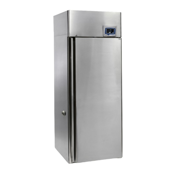
Bandejas (máximo) Potencia (CV) Consumo (W) 1350 1350 Peso (kg) DESCRIPCIÓN DEL EQUIPO Las estufas refrigeradas Hotcold F y J están construidas en acero inoxidable AISI 304. Son equipos de circulación forzada de aire que permiten: Estabilidad*: ±0,5ºC Homogeneidad*: ±1,3ºC Resolución:... -
Page 5: Instalación
INSTRUCTIONS MANUAL CODE 80411 REV 0 01/2022 Pag.: 5 Estas estufas se utilizan habitualmente para la conservación de productos en unas condiciones fijas. El equipo no genera humedad. Los ambientes muy secos pueden afectar el funcionamiento del equipo. INSTALACIÓN Colocar la estufa sobre una superficie plana, horizontal y nivelada, procurando dejar un espacio libre de 10 cm. - Page 6 MANUAL DE INSTRUCCIONES CÓDIGO 80411 REV 0 01/2022 Pag.: 6 Vista interior del armario INTERIOR CÁMARA: Luz interior. Ventilador para circulación forzada de aire. Orificio lateral para conexiones. CUADRO ELÉCTRICO: (parte posterior del equipo, zona superior) Magnetotérmico control, grupo de frío - calefacción Termostato de seguridad .P.
- Page 7 4‐ Ventilador para circulación forzada de aire 5‐ Sonda de humedad y temperatura 6‐ Estantes de altura graduable 7‐ Entrada lateral para sondas y equipos exteriores INSTRUCTIONS MANUAL CODE 80411 REV 0 01/2022 Pag.: 7 8‐ Tapón desagüe (SIEMPRE DEBE ESTAR TAPADO) 9‐ Anclajes de graduación de estantes FUNCIONAMIENTO Todas las funciones de equipo se establecen mediante la pantalla táctil. 7.3 – MANDOS POSTERIORES Presionar suavemente con el dedo en el centro de cada icono. ...
-
Page 8: Mantenimiento
MANUAL DE INSTRUCCIONES CÓDIGO 80411 REV 0 01/2022 Pag.: 8 PUESTA EN MARCHA: 1. Verificar que se ha seguido correctamente el protocolo de insta- lación. 2. Accionar el interruptor general (ver foto) que se encuentra en la parte posterior del equipo. Se iluminará la pantalla gráfica del controlador de temperatura MANTENIMIENTO Antes de quitar la tapa de la estufa para manipular en su interior,... - Page 9 INSTRUCTIONS MANUAL CODE 80411 REV 0 01/2022 Pag.: 9 TERMOSTATO DE SEGURIDAD 8. Tornillo de regulación del termostato de seguridad (gris). 9. Pulsador de rearme manual del termostato (blanco). Rearme del termostato de seguridad El termostato de seguridad es un elemento para prevenir que la temperatura exceda un valor.
-
Page 10: General Information
1001858 Instruction Manual 80411 ACCESSORIES Hotcold F and J equipments allow to connect stirrers and shakers without heating elements, which can be connected on inner sockets or through lateral hole. .P. SELECTA s.a.u. Autovía A-2 Km 585.1 Abrera 08630 (Barcelona) España Tel 34 937 700 877 Fax 34 937 702 362 e-mail: selecta@jpselecta.es - website: http://www.grupo-selecta.com... -
Page 11: Technical Features
Depth Shelves (maximum) Power (HP) Consumption (W) 1350 1350 Weight (kg) EQUIPMENT DESCRIPTION Hotcold F and J refrigerated cabinets are built in AISI 304 stainless steel. These are fan air circulation equipments which allow: Stability*: ±0.5ºC Homogeneity*: ±1.3ºC Resolution: ±0.1ºC Humidity: ±6%... -
Page 12: Installation
MANUAL DE INSTRUCCIONES CÓDIGO 80411 REV 0 01/2022 Pag.: 12 These cabinets are commonly used to preserve products under fixed con- ditions. The equipments do not generate humidity. Very dry environments can affect the operation of these equipments. INSTALLATION Place the cabinet on a flat horizontal, level surface, leaving a space of about 10 cm at the back and sides of the equipment. - Page 13 INSTRUCTIONS MANUAL CODE 80411 REV 0 01/2022 Pag.: 13 Inside view of the cabinet INNER CHAMBER: 1. Internal light. 2. Air circulating fan 3. Side hole for connections inlet. ELECTRICAL PANEL: (back upper side of the equipment) Magnetothermic control, cold - heating group and plugs. Safety thermostat .P.
- Page 14 6‐ Estantes de altura graduable 7‐ Entrada lateral para sondas y equipos exteriores 8‐ Tapón desagüe (SIEMPRE DEBE ESTAR TAPADO) 9‐ Anclajes de graduación de estantes MANUAL DE INSTRUCCIONES CÓDIGO 80411 REV 0 01/2022 Pag.: 14 7.3 – MANDOS POSTERIORES OPERATION All equipment functions are set using the touch screen. Gently press your 10‐ Interruptor general automático ICP finger in the center of each icon. ...
-
Page 15: Maintenance
INSTRUCTIONS MANUAL CODE 80411 REV 0 01/2022 Pag.: 15 STARTING UP: 1. Check that the installation protocol has been correctly followed. 2. Switch on the main switch (see picture) located on the back side of the equipment. The graphical display of the temperature controller will light up. - Page 16 MANUAL DE INSTRUCCIONES CÓDIGO 80411 REV 0 01/2022 Pag.: 16 SAFETY THERMOSTAT 8. Safety thermostat regulation screw (grey). 9. Safety thermostat reset button (white). Rearming the safety thermostat Safety thermostat is an element to prevent the temperature from exceeding a value. If by a fortuitous event the thermostat is triggered, that is, it opens the power circuit, the heating element will stop working.
Need help?
Do you have a question about the HOTCOLD F and is the answer not in the manual?
Questions and answers