Table of Contents
Advertisement
Quick Links
INSTALLATION, USE AND MAINTENANCE MANUAL
DUCTO - SLC
CANALIZED FANCOIL
Innova Srl
Via I Maggio, 8 - 38089 Storo (TN) - Tel. +39 0465 670104 - Fax +39 0465 674965 - info@innovaenergie.com
Share capital int. vers. € 150,000. - Tax code / VAT number 01827470228 - REA registration nr. 180610 - Reg. Companies (TN) 10656
Mechanographic number TN025148
www.innovaenergie.com
Page 1
N420355A_Manuale-SLC 2022_EN_Rev 03.docx
Advertisement
Table of Contents

Summary of Contents for Innova DUCTO - SLC
- Page 1 INSTALLATION, USE AND MAINTENANCE MANUAL DUCTO - SLC CANALIZED FANCOIL Innova Srl Via I Maggio, 8 - 38089 Storo (TN) - Tel. +39 0465 670104 - Fax +39 0465 674965 - info@innovaenergie.com Share capital int. vers. € 150,000. - Tax code / VAT number 01827470228 - REA registration nr. 180610 - Reg. Companies (TN) 10656 Mechanographic number TN025148 www.innovaenergie.com...
-
Page 2: Table Of Contents
AREAULIC CONNECTIONS ..............................12 AERAULIC CONNECTIONS WITH ACCESSORIES ........................14 AIR INTAKE ORIENTATION CHANGE ............................15 HYDRAULIC CONNECTIONS ................................16 GENERALITY ................................... 16 POSITIONING AND CONNECTION PROCEDURES ........................16 3-WAY VALVE CONNECTION ..............................17 Innova Srl Page 2 N420355A_Manuale-SLC 2022_EN_Rev 03.docx... - Page 3 PROBLEMS WITHOUT ERROR INDICATION ON THE DISPLAY ....................30 ALARM SIGNAL ..................................31 TABLE OF ALARMS SIGNALED BY DISPLAY - VERSIONS I -...................... 32 NOTES AND INFORMATION MAINTENANCE ........................... 33 NOTE ....................................... 33 Innova Srl Page 3 N420355A_Manuale-SLC 2022_EN_Rev 03.docx...
-
Page 4: Generality
The unit must be powered with electrical cables with a section suitable for the power of the unit. The voltage and frequency values must • correspond to those indicated for the respective machines; all the machines must be earthed as per the regulations in force in the various countries. Innova Srl Page 4 N420355A_Manuale-SLC 2022_EN_Rev 03.docx... -
Page 5: Symbology
It is recommended to use a dedicated power supply circuit; Never use a shared power supply with other appliances. It is recommended to install an earth leakage breaker; Failure to install this device may cause electric shock. Innova Srl Page 5... -
Page 6: Compliance
RoHS2 2011/65 / EU • WEEE 2012/19 / EC • 1.6 RANGE 1) Type of control 2) Defines the size S: 0-10v control From 400 - 1200 m³ / h I: electronics I Innova Srl Page 6 N420355A_Manuale-SLC 2022_EN_Rev 03.docx... -
Page 7: 1.7 Identification
Side condensate drain connections • Side inlet and outlet water connections • Labels / stickers (safety pictograms, channel identification, CE marking ...) already positioned on the unit. • Installation, use and maintenance manual • Innova Srl Page 7 N420355A_Manuale-SLC 2022_EN_Rev 03.docx... -
Page 8: Start-Up Requirements
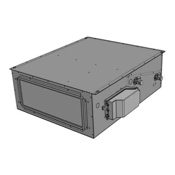
The main components of the unit are described below in order to understand the layout and characteristics of the machine. 1 Fan 2 Hydronic battery 3 Filter 4 Electrical connection box 5 Hydraulic connections 6 Condensate drain Innova Srl Page 8 N420355A_Manuale-SLC 2022_EN_Rev 03.docx... -
Page 9: Dimensional
1.12 DIMENSIONAL DUCTO - SLC 1000 1200 1190 1477 1150 1437 1170 1457 1060 1317 3/4 "F 3/4 "F 3/4 "F 3/4 "F 3/4 "F IN WATER 3/4 "F 3/4 "F 3/4 "F 3/4 "F 3/4 "F OUT WATER EXHAUST V Ø... -
Page 10: Installation
Ensure sufficient space for carrying out maintenance • activities: the opening of the unit cover (from below) and accessibility to the electrical box and to the hydraulic connections must be guaranteed; Innova Srl Page 10 N420355A_Manuale-SLC 2022_EN_Rev 03.docx... -
Page 11: 2.3 Condensate Drain Connection
For the heat recovery unit to function correctly, a condensate drain must be connected to the plumbing system (drain) of the house. Furthermore, to allow the condensate water to flow correctly and avoid unpleasant odors, the condensate drain must always be equipped with the appropriate siphon to be placed on the drain line by the installer; Innova Srl Page 11 N420355A_Manuale-SLC 2022_EN_Rev 03.docx... -
Page 12: Areaulic Connections
For the correct connection of the air ducts, refer to the following diagram and the stickers placed on the unit. Horizontal installation The configurations for the aeraulic flows and connections are indicated on the side: Air delivery Air intake Innova Srl Page 12 N420355A_Manuale-SLC 2022_EN_Rev 03.docx... - Page 13 B. Shooting - Base x Height mm 460 x 120 660 x 120 860 x120 1060x120 1320x120 We recommend installing at least 500 mm of flexible piping to avoid entrainment of vibrations and annoying noises due to installation Innova Srl Page 13 N420355A_Manuale-SLC 2022_EN_Rev 03.docx...
-
Page 14: Aeraulic Connections With Accessories
4 x 160 6 x 160 7 x 160 D. Return Plenum - Number of connections / Diameter mm 2 x 160 3 x 160 4 x 160 6 x 160 7 x 160 Innova Srl Page 14 N420355A_Manuale-SLC 2022_EN_Rev 03.docx... -
Page 15: Air Intake Orientation Change
NB Always carry out these operations with the unit disconnected and the motor stopped. Change of air intake orientation Innova Srl Page 15 N420355A_Manuale-SLC 2022_EN_Rev 03.docx... -
Page 16: Hydraulic Connections
The hydraulic connections are located on the side of the unit. The connections are with Eurokonus ¾ ”male thread. Respect IN as the water inlet to the unit and OUT as the water outlet from the unit. Innova Srl Page 16 N420355A_Manuale-SLC 2022_EN_Rev 03.docx... -
Page 17: 3-Way Valve Connection
The groups are supplied as a kit to be assembled and contain all the fittings to facilitate the connection to the installer. 3-way valve group kit Two-way valve assembly kit Innova Srl Page 17 N420355A_Manuale-SLC 2022_EN_Rev 03.docx... -
Page 18: Generality
POSITIONING AND CONNECTION PROCEDURES On the side of the unit there is the electrical box for the electrical connections, while inside the box there are the cable clamps and the screws supplied. Electrical connections Innova Srl Page 18 N420355A_Manuale-SLC 2022_EN_Rev 03.docx... -
Page 19: S Version Unit Wiring Diagrams - (0-10V Dc Command)
S VERSION UNIT WIRING DIAGRAMS - (0-10V DC COMMAND) S versions wiring diagram CONNECTIONS BY THE CUSTOMER L - N - PE Power supply 230/1/50 Check power in the previous tables Voltage supplied by the motor Reference voltage signal (I max = 20 ma) 0-10v dc signal to the motor Reference signal Page 19... -
Page 20: Version I Unit Wiring Diagrams - (Electronic Board)
VERSION I UNIT WIRING DIAGRAMS - (ELECTRONIC BOARD) Wiring diagram I versions CONNECTIONS BY THE CUSTOMER Window contact Contact closed / Unit on GRID Contact presence Contact closed / unit off Clean Contact Generator / pump consent CHILLER (hot / cold request activation) Water valve / post battery Live contact (220v) WATER VALVE (N-EV1) -
Page 21: Electrical Connections Version -I
ELECTRICAL CONNECTIONS VERSION -I- CNV-CNW remote panel connection The -I- version card provides remote controls of the capacitive Touch type to manage all the unit functions and are designed for installation on the wall or outside the 502 box. There are two families of remote commands: EEA649II / EEB649II - Serial control with •... - Page 22 DISPLAY CONNECTION TO CONTROL MULTIPLE UNITS The EEA649II / EEB649II - EFA649II / EFB649II panel provides for the command of several units; it is possible to connect up to 30 units which will be managed by a single remote panel; They must be connected in series with an in and out connection on the boards of the individual units;...
- Page 23 UNIT REMOTE ON OFF CONNECTION It is possible to connect an external on off contact to the unit which provides for the unit to be stopped; Contact Closed: unit OFF Screw terminals Recommended cable = 2x0.5mm / 2 x 0.75mm Remote On off contact VALVE CONNECTION The unit provides for the control of a 2 or 3-...
- Page 24 MODBUS RTU CONNECTION TO THE UNIT Without connecting the display, the machine can be connected to a Modbus RS485 RTU supervision system; The communication protocol is: RTU 9600 N 8 1; Screw terminals Recommended cable = 2x0.5 mm shielded Modbus RTU unit connection MODBUS RTU CONNECTION TO REMOTE PANEL T / H With the connection of the remote panel, the machine can be connected to a supervision...
-
Page 25: Commissioning And Method Of Use
COMMISSIONING AND METHOD OF USE OPERATION VERSION –S- The unit is completely manually controlled by the user, through an external control system; Through the 0-10v dc input signal, the motor behaves as in the figure alongside; Operation S versions OPERATION VERSION -I- The unit is completely manually controlled by the user, through the wall-mounted touch control EEA649II / EEB649II -... -
Page 26: Turning The Unit On And Off
TURNING THE UNIT ON AND OFF -The unit can be enabled and disabled using the On / Off button on the display. Unit ON / OFF MODIFICATION OF FANS SPEED AND BOOSTER FUNCTION -On the display there are keys for selecting the desired speed of the unit; Each time the speed is selected, the actual fan speed variation occurs after 1 second. -
Page 27: Key Lock
KEY LOCK Pressing the + and - keys simultaneously for 3 seconds activates the local lock of all the keys, confirmation is given by the display of the message bL. All adjustments are disabled for the user and bL appears when any key is pressed. By repeating the sequence, the keys are unlocked. -
Page 28: Maintenance
MAINTENANCE To always ensure correct and optimal operation of the unit, all maintenance interventions must be carried out periodically. CLEANING OR REPLACING FILTERS VERSION WITHOUT ACCESSORIES To replace the filters or to clean them, proceed as follows: disconnect the unit from the power supply; •... -
Page 29: General Cleaning Of The Unit
GENERAL CLEANING OF THE UNIT It is advisable to occasionally check and, if necessary, clean the fans, the condensate drain and the internal walls of the unit. These operations must only be carried out by qualified personnel (installer). To carry out the above operations, proceed as follows: disconnect the unit from power supply •... -
Page 30: Alarms
ALARMS GENERALITY In case of problems or breakdowns, take note of any error code appearing on the display of the electronic control unit or of the remote control, take note of the model and serial number of the unit you own (present on the identification plate attached to the side of the unit) and contact the installer. -
Page 31: Alarm Signal
ALARM SIGNAL Below is a list of all the alarms managed by the application. The presence of an alarm has two display modes: an error code present on the EEA649II / EEB649II - EFA649II / EFB649II command; • a led on the electronic board that shows a flashing sequence with the type of alarm present. •... -
Page 32: Table Of Alarms Signaled By Display - Versions I
TABLE OF ALARMS SIGNALED BY DISPLAY - VERSIONS I - Below is the table of the unit operating anomalies signaled, in the electronic versions I by the remote display or by the flashing of the LED on the board. CODE DESCRIPTION CAUSE REMEDY... -
Page 33: Notes And Information Maintenance
NOTES AND INFORMATION MAINTENANCE NOTE ____________________________________________________________________________________________________________________________________________________________________________________________________ ____________________________________________________________________________________________________________________________________________________________________________________________________ ____________________________________________________________________________________________________________________________________________________________________________________________________ ____________________________________________________________________________________________________________________________________________________________________________________________________ ____________________________________________________________________________________________________________________________________________________________________________________________________ ____________________________________________________________________________________________________________________________________________________________________________________________________ ____________________________________________________________________________________________________________________________________________________________________________________________________ ____________________________________________________________________________________________________________________________________________________________________________________________________ ____________________________________________________________________________________________________________________________________________________________________________________________________ ____________________________________________________________________________________________________________________________________________________________________________________________________ 01- 20 21 N 4 20 43 1A - 03 The data contained in this manual can be changed by the manufacturer without prior notice. Page 33...
Need help?
Do you have a question about the DUCTO - SLC and is the answer not in the manual?
Questions and answers