Table of Contents
Advertisement
Quick Links
Congratulations !
Your new miniCHEM-Cond monitor is the latest in simple, reliable process
monitoring instrumentation. With correct operation and maintenance, your
miniCHEM-Cond will give you many years of reliable service.
The miniCHEM-Cond is a breeze to operate. This manual has been designed to
help you get started, and also contains some handy application tips. If at any
stage you require assistance, please contact either your local TPS representative
or the TPS factory in Brisbane.
The manual is divided into the following sections:
1. Table of Contents
Each major section of the handbook is clearly listed. Sub-sections have also
been included to enable you to find the information you need at a glance.
2. Introduction
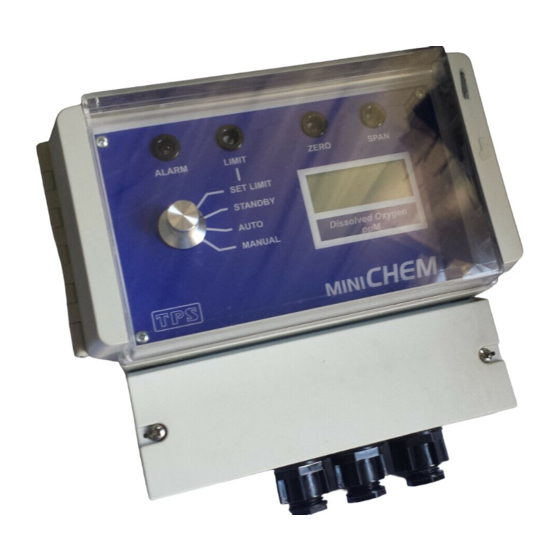
The introduction has a diagram and explanation of the display and controls of
the miniCHEM-Cond. It also contains a full listing of all of the items that
you should have received with the unit. Please take the time to read this
section, as it explains some of items that are mentioned in subsequent
sections.
3. Main Section
The main section of the handbook provides complete details of the
miniCHEM-Cond, including operating modes, calibration, troubleshooting,
specifications, and warranty terms.
4. Appendices
Appendices containing background information and application notes are
provided at the back of this manual.
miniCHEM-Cond
Process Monitor
Version
: 2.01
Date
: 16-Jul-2002
Author
: MS
Advertisement
Table of Contents
Troubleshooting

Subscribe to Our Youtube Channel
Related Manuals for TPS miniCHEM-Cond


Summary of Contents for TPS miniCHEM-Cond
- Page 1 The introduction has a diagram and explanation of the display and controls of the miniCHEM-Cond. It also contains a full listing of all of the items that you should have received with the unit. Please take the time to read this section, as it explains some of items that are mentioned in subsequent sections.
- Page 2 Page 2 TPS Pty Ltd ABN 30 009 773 371 4 Jamberoo Street Springwood, Brisbane, Australia, 4127 Phone : (07) 32 900 400 International : 61 7 32 900 400 : (07) 3808 4871 International : 61 7 3808 4871 Email : tps@tps.com.au...
-
Page 3: Table Of Contents
Page 3 Contents Introduction ....................4 1.1 miniCHEM-Cond Illustration................4 1.2 Unpacking Information ..................6 1.3 Specifications....................7 Operating Modes ..................8 Installation and Set-up ................9 3.1 Connection and Configuration Diagram ............9 3.2 Mounting the Enclosure ..................10 3.3 Mounting the Sensor ..................10 3.4 Terminal Connections ..................11 3.5 Setting the Control Limit ................12... -
Page 4: Introduction
Page 4 1. Introduction 1.1 miniCHEM-Cond Illustration... - Page 5 The Function Switch is used to select the mode of operation. See section 2. ± Display Window The miniCHEM-Cond has a large, easy to read LCD display. The units of measurement are clearly shown in the window beneath the display. Æ...
-
Page 6: Unpacking Information
Page 6 1.2 Unpacking Information Before using your new miniCHEM-Cond, please check that the following accessories have been included: Part No 1. miniCHEM-Cond Process Monitor ....... 112140 2. miniCHEM-Cond Handbook ........ 130050 3. Conductivity standard to suit customer-specified range Options that may have been ordered with your miniCHEM-Cond: Conductivity Sensors…... -
Page 7: Specifications
Page 7 1.3 Specifications Ranges k=0.1 Sensor....0 to 19.99 µS/cm, 0 to 199.9 µS/cm or 0 to 1999 µS/cm k=1.0 Sensor....0 to 199.9 µS/cm,0 to 1999 µS/cm, or 0 to 19.99 mS/cm k=10 Sensor....0 to 1999 µS/cm, 0 to 19.99 mS/cm, or 0 to 199.9 mS/cm Resolution ................0.05% of full scale Accuracy ................±0.2% of full scale Linearity................±0.05% of full scale... -
Page 8: Operating Modes
: Switch to MANUAL to manually dose chemicals or water when the optional relay output is fitted. The relay output will be activated for as long as the miniCHEM-Cond is in this mode, regardless of the Conductivity reading. See section 7. -
Page 9: Installation And Set-Up
Page 9 3. Installation and Set-up 3.1 Connection and Configuration Diagram The diagram below is provided as a reference for the terminal connections, configuration jumpers and user-adjustable trimmers that are discussed throughout this section. -
Page 10: Mounting The Enclosure
Page 10 3.2 Mounting the Enclosure The miniCHEM-Cond can be wall-mounted with 3 screws. Two mounting points are located underneath the terminal cover, and are positioned so that they do not affect the waterproofing of the enclosure. The third mounting point is centrally located near the top of the rear of the enclosure, and has been designed to hook over a screw-head. -
Page 11: Terminal Connections
Page 11 3.4 Terminal Connections Note: The power connections detailed below are for normal mains power. Refer to section 11.3 for power wiring details when the 12V DC power option is fitted. Terminal No. Connection Colour Conductivity Sensor ATC Blue Conductivity Sensor ATC White No Connection... -
Page 12: Setting The Control Limit
Page 12 3.5 Setting the Control Limit The control limit can be set over the full scale of the miniCHEM-Cond, as a “too high” or a “too low” trip point. The hysteresis around this set point can be also be adjusted, if necessary. - Page 13 ±40 digits with the HYSTERESIS trimmer in the terminal area. Turning the HYSTERESIS clockwise increases the hysteresis and turning it anti-clockwise decreases the hysteresis. TPS DOES NOT recommend that this setting be altered, unless it is absolutely necessary. The HYSTERESIS trimmer should only be adjusted a little at time. The process being controlled should then be closely monitored over a time to ensure that the desired control is being achieved.
-
Page 14: Selecting Current Or Voltage Output
The jumper settings for 0 to 1V DC output are: Note that the spare jumper has been fitted to a spare Current/Voltage Output jumper pin. This is a safe place to keep it, in case the miniCHEM-Cond needs to be reset to current output in the future. -
Page 15: Calibrating The 4 To 20Ma Output
TPS has provided calibration controls for the 4mA and 20mA points in case this requires adjustment in the field. Only a limited amount of adjustment is available, as the miniCHEM-Cond is designed for 4 to 20mA output for the full scale of the instrument. -
Page 16: Calibration
Page 16 4. Calibration 4.1 Calibration Procedure 1. Switch the miniCHEM-Cond on. 2. Ensure that the Conductivity sensor is correctly connected (see section 3.4). 3. Set the function switch to STANDBY, to ensure that the (optional) relay output is not activated when moving the Conductivity sensor between solutions. -
Page 17: Calibration Notes
10. When the reading has stabilised, adjust the SPAN control until the display shows the value of the standard. 11. Rinse the Conductivity sensor in distilled water and blot dry. 12. The miniCHEM-Cond is now calibrated and ready for Conductivity measurements. 4.2 Calibration Notes 1. -
Page 18: Process Monitoring
Page 18 5. Process Monitoring Once the miniCHEM-Cond has been installed, connected and calibrated, it can be used for continuous monitoring. To monitor the process, WITHOUT any control or alarm functions switch the function switch to STANDBY. 6. Automatic Dosing For Automatic Alarming or Control, switch the function switch to AUTO to enable the Alarm LED and the (optional) relay output. -
Page 19: Troubleshooting
2. Mains power input Check connections (see section incorrectly connected. 3.4). 3. Instrument is faulty. Return to TPS for repair. Alarm LED or 1. Limit not set correctly for Set the Lo/Hi Output jumpers (optional) relay “too high” or “too low”... -
Page 20: Conductivity Troubleshooting
Page 20 9.2 Conductivity Troubleshooting Symptom Possible Causes Remedy Zero calibration 1. Electrode has Zero error. Thoroughly rinse electrode in fails (insufficient distilled water and allow to range with ZERO completely dry in air before attempting zero calibration. control). If instrument does not calibrate at Zero with electrode disconnected, then the instrument is faulty. - Page 21 Page 21 Conductivity Troubleshooting, continued… Inaccurate 1. Electrode may have a Clean electrode, as per the readings, even build-up of dirt or oily instructions detailed in section when calibration is material on electrode 11.2.2. successful. wires. Electrode requires 2. Platinum-black coating has replatinisation.
-
Page 22: Warranty
TPS Pty. Ltd. has a fine reputation for prompt and efficient service. In just a few days, our factory service engineers and technicians will examine and repair your equipment to your full satisfaction. - Page 23 Page 23 Please check that the following is enclosed with your equipment: • Your Name and daytime phone number. • Your company name, ORDER number, and return street address. • A description of the fault. (Please be SPECIFIC.) (Note: "Please Repair" does NOT describe a fault.) Your equipment will be repaired and returned to you by air express where possible.
-
Page 24: Appendices
11. Appendices 11.1 Re-setting the Display Range The range of the miniCHEM-Cond may be re-set using the table of jumper settings shown below. Refer to the diagram in section 3.1 for the location of the A, B and Decimal Point jumper blocks. Attach spare jumpers off single unused pins for safe storage. -
Page 25: Care, Cleaning And Maintenance Of Conductivity Electrodes
11.2 Care, Cleaning and Maintenance of Conductivity Electrodes 11.2.1 Care of Conductivity electrodes The conductivity section of the electrode supplied with your miniCHEM-Cond consists of two platinum wires that are plated with a layer of “platinum-black”. This is quite a soft layer and is required for stable, accurate measurements. In time, the platinum-black layer may wear off in some applications, at which time the electrode will require replatinising (see section 11.2.3). - Page 26 Page 26 11.2.2 Cleaning of Conductivity of Electrodes Platinised platinum Conductivity electrodes can only be cleaned by rinsing in a suitable solvent. DO NOT wipe the electrode wires, as this will remove the platinum-black layer. 1. Rinsing in distilled water will remove most build-ups of material on the electrode wires.
- Page 27 11.2.3 Replatinising Conductivity Electrodes There are several ways to replatinise Conductivity electrodes. 1. The simplest way is to return the electrode to the TPS factory. We can fully clean the electrode, replatinise it and test all aspects of its performance.
-
Page 28: Terminal Connections When 12V Dc Option Is Fitted
Page 28 11.3 Terminal connections when 12V DC option is fitted Terminal No. Connection Colour Conductivity Sensor ATC Blue Conductivity Sensor ATC White No Connection Guard Shield/Braid (only fitted for very long sensor cable) Conductivity Sensor Cell Black Conductivity Sensor Cell +ve of current or voltage output Customer-defined -ve of current or voltage output... -
Page 29: Relay Output Wiring Examples For Mains Powered Units
Page 29 11.4 Relay Output Wiring Examples for mains powered units The diagrams below provide some examples of wiring the (optional) relay output for standard mains powered miniCHEM-Cond units. -
Page 30: Relay Output Wiring Examples For 12V Dc Powered Units
Page 30 11.5 Relay Output Wiring Examples for 12V DC powered units The diagrams below provide some examples of wiring the (optional) relay output for miniCHEM-Cond units with the 12V DC power option. -
Page 31: Drilling Template
Page 31 11.6 Drilling Template The template below is for the three mounting positions for the miniCHEM enclosure. This template is actual size, and can be photocopied or removed as required. - Page 32 Page 32...
Need help?
Do you have a question about the miniCHEM-Cond and is the answer not in the manual?
Questions and answers