Advertisement
Instruction Manual
1. Safety Instructions
•
To ensure sufficient convection cooling, always maintain a safety distance of ≥ 50mm from
all ventilated surfaces while the device is in operation.
•
The device is not recommended to be placed on low thermal conductive surface, for
example, plastics.
•
Note that the enclosure of the device can become very hot depending on the ambient
temperature and load of the power supply. Do not touch the device while it is in operation
or immediately after power is turned OFF. Risk of burning!
•
Do not touch the terminals while power is being supplied. Risk of electric shock.
•
Prevent any foreign metal, particles or conductors from entering the device through the
openings during installation. It may cause: Electric shock; Safety Hazard; Fire; Product
failure
•
Warning: When connecting the device, secure Earth connection before connecting L and
N. When disconnecting the device, remove L and N connections before removing the Earth
connection.
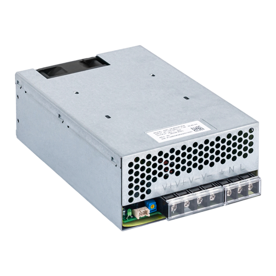
2. Device Descriptions
Refer to Fig. 1.:
� Input terminal block connector
� Output terminal block connector
� DC voltage adjustment potentiometer
Signal Connector
DC OK control LED (Green)
⑥ DC Fan
3. Installation of the Device
The unit is protected with internal fuse (not replaceable) at L pin and it has been tested
and approved on 20A (UL) and 16A (IEC) branch circuits without additional protection device.
Refer to Fig. 2.:
� Mounting holes for power supply assembly onto the mounting surface. The power supply
shall be mounted on minimum 4 mounting holes using M4 screw.
� Input / Output connector
� This surface belongs to customer's end system or panel where the power supply is
mounted.
•
Use flexible cable (stranded or solid) of AWG No. 14-10. The torque at the Input connector
shall not exceed 11.98Kgf.cm. The torque at the Output connector shall not exceed
16.59Kgf.cm. The insulation stripping length should not exceed 0.275" or 7mm (Refer to
Fig. 3).
4. Installation of Mounting Accessories
Refer to Fig. 4.:
•
Only use M4 screw ≤ 4.5mm through the base mounting holes. This is to keep a safe
distance between the screw and internal components.
•
Recommended mounting torque for tightening: 4~8Kgf.cm.
5. Input Voltage Derating Curve
•
Output derating is required at 85-110Vac (Refer to Fig. 5).
6. Maximum 5000 Meters Operating Altitude
REV. 00
All manuals and user guides at all-guides.com
B
C
Air flow direction
6
Base surface
Fig. 1. Device Descriptions
Side Mounting
Base Mounting
(Horizontal)
C
A
A
Fig. 2 Mounting Orientations
Lug
Fig. 3. Wire Type
Mounting
Chassis of
accessories
the device
Mounting
screw
4.5mm
Xmm max.
max.
Fig. 4. Mounting Screw
PMC-24V600W1RW
Top surface
Side surface
1
2
3
4
5
Base Mounting
Base Mounting
(Vertical)
(Vertical)
C
B
B
A
A
7mm max.
Stripped Wire
Load (%)
100
80
85
11
0
Fig. 5. Input Voltage Derating Curve
www.DeltaPSU.com
C
B
(Vac)
Advertisement
Table of Contents

Related Manuals for Delta PMC-24V600W1RW


Summary of Contents for Delta PMC-24V600W1RW
- Page 1 All manuals and user guides at all-guides.com Instruction Manual PMC-24V600W1RW 1. Safety Instructions Air flow direction • To ensure sufficient convection cooling, always maintain a safety distance of ≥ 50mm from Top surface all ventilated surfaces while the device is in operation.
- Page 2 All manuals and user guides at all-guides.com PMC-24V600W1RW 使用说明书 使用说明书 取扱説明書 取扱説明書 1. 1. 安全规范 安全规范 1. 安全上の注意 安全上の注意 与通风表面保持至少 50mm 的安全距离,以确保对流冷却充分。 電源装置を十分に冷却するため、運転中はすべての通気面の周囲に 50mm 以上のス • • • 本产品不适合摆放在低热导体,例如: 塑胶。 ペースを保って下さい。 • 受环境温度及产品负载的影响,本机外壳温度会很高,因此在上电时或切断电源后短 • 本装置を低熱伝導面(例: プラスチック)に設置することは避けて下さい。 时间内不要触摸本机,以免烫伤。 • 電源装置の周囲を囲うと、周囲温度や電源の負荷によって非常に熱くなることがあ •...
Need help?
Do you have a question about the PMC-24V600W1RW and is the answer not in the manual?
Questions and answers