Advertisement
Quick Links
Advertisement

Related Manuals for Tektronix 7000-series


Summary of Contents for Tektronix 7000-series
- Page 1 Ö DIGITAL COUNTER Tektronix, Inc. •...
- Page 3 TABLE OF CONTENTS...
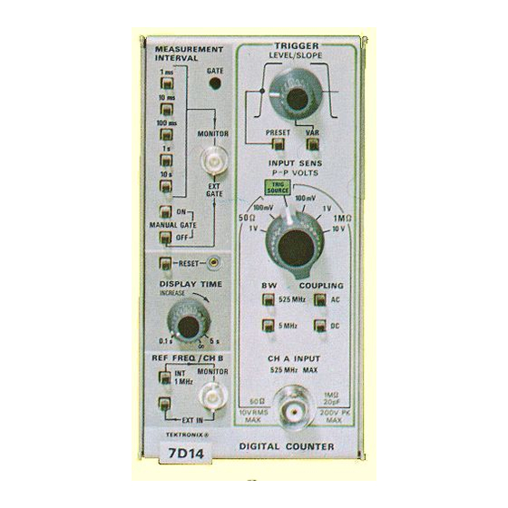
- Page 4 7D14...
-
Page 5: Section 1 Specifica Tion
SECTION 1 SPECIFICA TION Change information, if any, affecting this section will be found at the rear of this manual. - Page 10 SECTION OPERATING INSTRUCTIONS Change information, if any, affecting this section will be found at the rear of this manual.
- Page 13 NOTE The First-Time Operation procedure along with Table 2-1 can be used to provide a confidence check of the instrument's operation. These steps should be per formed each time the 7D14 is placed in a different oscilloscope, and before each use.
-
Page 21: Section 3 Circuit Description
SECTION 3 CIRCUIT DESCRIPTION Change information, if any, affecting this section will be found at the rear of this manual. NOTE All references to direction of current in this manual are in terms of conventional current; i.e., from plus to minus. - Page 34 U>...
-
Page 45: Section 4 Maintenance
SECTION 4 MAINTENANCE Change information, if any, affecting this section will be found at the rear of this manual. Avoid the use of chemical cleaning agents which might damage the plastics in this instrument. Avoid chemicals containing benzene, toluene, xylene, ace tone, or similar solvents. - Page 48 component may affect its performance in the instru ment. All replacement parts should be direct replace ments unless it is known that a different component will not adversely affect the instrument performance. Do not use an ohmmeter scale that has a high internal current.
- Page 49 open-end CAUTION < When disconnecting or connecting leads to a wafer type rotary switch, do not let solder flow around and beyond the rivet on the switch terminal. Excessive solder can destroy the spring tension of the contact.
- Page 51 SECTION S CALIBRATION Change information, if any, affecting this section will be found at the rear of this manual.
- Page 54 NOTE The performance of this instrument can be checked at any temperature within the 0° C to +50° C range unless stated otherwise.
- Page 55 NOTE This procedure checks the 7D14 frequency range to 500 MHz. To check the frequency range to the maxi mum limit as given under Performance Requirement ection 1, use a constant-amplitude generator with NOTE at least a 525-MHz output. In steps one through four, the exact reading obtained depends on the accuracy of the generator dial setting.
- Page 58 µs/...
- Page 62 NOTE This instrument should be adjusted at an ambient temperature of 25° C ±5°C for best overall accuracy. NOTE Titles for external controls of this instrument are capitalized in this procedure (e.g., INPUT EN ). Internal adjustments are initial capitalized only (e.g., Ref Voltage).
- Page 66 NOTE The oscillator frequency must be adjusted at an ambient room temperature of about +2tfC according to the following procedure to ensure operation within the limits given in ection 1 for an operating tempera ture range of 0° C to +50° C.
-
Page 72: Electrical Parts List
SECTION 6 ELECTRICAL PARTS LIST µF µF... - Page 74 µF µF µF µF µF µF µF µF µF µF µF µF µF µF µF µF µF...
- Page 76 2.7 µH 8 µH 8 µH 70-72 70-72...
- Page 77 Q407...
- Page 79 Prec -0159-00...
- Page 94 SECTION...
- Page 95 NOTE The spring tension of the pin sockets ensures a good connection between the circuit board and pin. This spring tension may be damaged by using the pin sockets as a connecting point for spring-loaded probe tips, alligator dips, etc.
- Page 97 ------------------------------...
- Page 101 «ç y 11" \JKR363 1 Qi88j8l ! Jt^SiciäöS^ ■ T" ‘ V...
- Page 105 »OI Q251 rmr^- j<j>...
- Page 107 ' 7 - a &...
- Page 108 30S,...
- Page 109 - R 860 ‘ 'AiSO/ --RSgi-'jX*...
- Page 111 à! , U54! , L/ 2O, L/54O...
- Page 112 t> >1...
- Page 115 Q680...
- Page 117 I > <<■ aQLV...
- Page 118 A p n a r=i a □ a a ' U72.5Ä 7 6 ¾04C 'A S04G V¾¾04t...
- Page 119 <r <$> U < ! " r T" ♦ ♦ ‘ • ¾ ’ -j » ”...
- Page 121 □ □ □□□□□□ □□□□□□□□□□□ □ □□...
- Page 122 5T 3; vwx ' y z...
- Page 123 Assembly and/or Component Detail Part of Assembly and/or Component mounting hardware for Detail Part Parts of mounting hardware for Parts of Detail Part mounting hardware for Assembly and/or Component...
- Page 124 (parts list combined with illustration)
-
Page 125: Mechanical Parts List
SECTION 8 MECHANICAL PARTS LIST (not included w/knob) w/hardware included w/resistor) (not included w/resistor) (not included w/switch) - Page 126 (not included w/circuit board assembly) (not included w/circuit board assembly) (not included w/circuit board assembly) (not included w/circuit board assembly) (not included w/circuit board assembly) included w/subpanel) w/hardware...
- Page 127 Disc (not included w/heat sink) (not included w/oscillator) (not included w/circuit board assembly) (not included w/panel) (brown) (red) (green)
- Page 128 (orange) (blue) (yellow) (gray) (white) (violet) (not shown)
- Page 133 7D14 EFF SN B030000-up ELECTRICAL PARTS LIST AND SCHEMATIC CORRECTION Al HIGH FREQ COUNTER Circuit Board Assembly CHANGE TO: 151-0367-00 Q364 Silicon SKA6516 Q376 151-0367-00 Silicon SKA6516 Q384 151-0367-00 Silicon SKA6516 Q392 151-0367-00 Silicon SKA6516 Q402 151-0367-00 Silicon SKA6516 R332 315-0132-00 1.3 kΩ...
Need help?
Do you have a question about the 7000-series and is the answer not in the manual?
Questions and answers