
Related Manuals for AC Pro AWHD(18)ND3GO

Summary of Contents for AC Pro AWHD(18)ND3GO
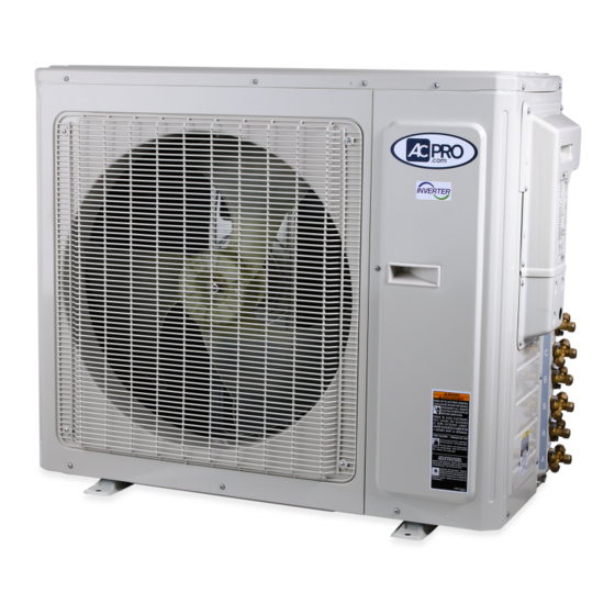
- Page 1 AC Pro Multi-Zone Outdoor 18-24K Service Manual AWHD(18)ND3GO AWHD(24)ND3GO (Refrigerant R410A)
-
Page 3: Table Of Contents
Table of Contents Part Ⅰ : Technical Information 1. Summary 2. Specifications 3. Outline Dimension Diagram 4. Refrigerant System Diagram 5. Electrical Part 5.1 Wiring Diagram 5.2 PCB Printed Diagram 6. Function and Control Part Ⅱ : Installation and Maintenance 7. -
Page 4: Part Ⅰ : Technical Information
Ⅰ : Technical Information PART I : TECHNICAL INFORMATION 1. SUMMARY Summary utdoor Unit GWHD(18)ND3EO GWHD(18)ND3FO Outdoor Unit GWHD(18)ND3GO AWHD(18)ND3GO GWHD(24)ND3EO GWHD(24)ND3FO GWHD(24)ND3GO AGWHD(24)ND3GO hnical Information Technical Information... -
Page 5: Specifications
2. SPECIFICATIONS Model AWHD(18)ND3GO Product Code CB228W07700 Rated Voltage 208/230 Power Supply Rated Frequency Phases Cooling Capacity (max~min) Btu/h 18000(6155~6998) Heating Capacity (max~min) Btu/h 19000(8530~22600) Cooling Power Input (max~min) 1440 Heating Power Input (max~min) 1520 Cooling Current Input 6.62 Heating Current Input 6.61... - Page 6 Connection Pipe Connection Method Flare Connection Not Additional Gas Connection Pipe Length 131.2 Connection Pipe Gas Additional Charge oz/ft. Outer Diameter of Liquid Pipe1(AC Pro Allocation) inch (Metric) Outer Diameter of Liquid Pipe2(AC Pro Allocation) inch (Metric) Outer Diameter of Gas Pipe1(AC Pro Allocation)(Metric)
- Page 7 Model AWHD(24)ND3GO Product Code CB228W07800 Rated Voltage 208/230 Power Supply Rated Frequency Phases Cooling Capacity (max~min) Btu/h 24000(7500~33000) Heating Capacity (max~min) Btu/h 26000(7500~35000) Cooling Power Input (max~min) 1920 Heating Power Input (max~min) 2050 Cooling Current Input 8.35 Heating Current Input Rated Power Input 4550 Current Breaker...
- Page 8 Connection Pipe Connection Method Flare Connection Not Additional Gas Connection Pipe Length 98.4 Connection Pipe Gas Additional Charge oz/ft. Outer Diameter of Liquid Pipe1(AC Pro Allocation) inch (Metric) Outer Diameter of Liquid Pipe2(AC Pro Allocation) inch (Metric) Outer Diameter of Liquid Pipe2(AC Pro Allocation)
-
Page 9: Outline Dimension Diagram
Service Manual utline Dimension Diagram 3. OUTLINE DIMENSION DIAGRAM AWHD(18)ND3GO D(18)ND3EO GWHD(18)ND3FO GWHD(18)ND3GO 35 1/8 13 27/64 15 39/64 Unit:inch AWHD(24)ND3GO WHD(24)ND3EO GWHD(24)ND3FO GWHD(24)ND3GO 13 27/64 35 1/8 17 21/64 38 37/64 Unit:inch Technical Information Technical Information... -
Page 10: Refrigerant System Diagram
4. Refrigerant System Diagram 4. REFRIGERANT SYSTEM DIAGRAM outdoor indoor filter A heat exchanger filter outdoor heat exchanger 4-way valve B heat exchanger filter high pressure switch Note: Not available for 14K/18K model discharge silencer C heat exchanger discharge temperature sensor filter D heat exchanger... -
Page 11: Electrical Part
COMP Compressor Violet Orange Yellow Brown Grounding wire Blue YEGN Yellow/Green Black Violet Orange ● Outdoor Unit OUTDOOR UNIT AWHD(18)ND3EO AWHD(18)ND3FO AWHD(18)ND3GO GWHD(18)ND3EO GWHD(18)ND3FO GWHD(18)ND3GO TERMINAL POWER BLOCK L2 L3 EXHAUST AC-L1 θ TEMP.SENSOR AC-L2 AC-L OUTROOM T-SENSOR θ YEGN E(PE) TEMP.SENSOR... - Page 12 e Manual AWHD(24)ND3EO AWHD(24)ND3FO AWHD(24)ND3GO GWHD(24)ND3EO GWHD(24)ND3FO GWHD(24)ND3GO 63633609 These circuit diagrams are subject to change without notice, please refer to the one supplied with the unit. These circuit diagrams are subject to change without notice, please refer to the one supplied with the unit. Technical Information Technical Information...
-
Page 13: Pcb Printed Diagram
5.2 PCB Printed Diagram 5.2 PCB PRINTED DIAGRAM GWHD(18)ND3EO GWHD(18)ND3FO GWHD(18)ND3GO AWHD(18)ND3EO AWHD(18)ND3FO AWHD(18)ND3GO ● TOP VIEW Terminal of compressor No Name Terminal of low-temperature cooling temperature sensor Terminal of compressor Overload protection terminal of compressor Terminal of low- Temperature sensor terminal... - Page 14 GWHD(24)ND3EO GWHD(24)ND3FO GWHD(24)ND3GO AWHD(24)ND3EO AWHD(24)ND3FO AWHD(24)ND3GO ● TOP VIEW 2 3 4 1 Terminal of compressor No Name 2 Low pressure protection terminal Terminal of compressor 3 High pressure protection terminal 4 Overload protection terminal of Low pressure protection compressor terminal 5 Temperature sensor terminal of High pressure protection...
-
Page 15: Function And Control
6. FUNCTION AND CONTROL FUNCTION CONTROL Cooling mode • If the compressor is stopped and the indoor unit reaches the cooling operation condition; the electronic expansion valve, the outdoor fan and the compressor will all begin to operate. • If the compressor stops suddenly, the outdoor fan will stop within 1 minute. •... - Page 16 2.3 Discharge Protection Function • When the discharge temperature is low, the compressor raises the operational frequency. When the discharge temperature is high, the compressor frequency is restricted or lowers the operational frequency; when the discharge temperature is too high, the compressor protection stops running. •...
-
Page 17: Part Ⅱ : Installation And Maintenance
PART II : TECHNICAL INFORMATION 7. NOTES FOR INSTALLATION AND MAINTENANCE SAFETY PRECAUTIONS: manufacturer before proceeding with installation or repair. DO NOT elongate these wires. IMPORTANT! 11. An air switch MUST be installed if there is no plug found Please read the safety precautions carefully before on the air conditioner. - Page 18 MAIN TOOLS FOR INSTALLATION AND MAINTENANCE 1. Level meter, measuring 2. Screwdrivers 3. Impact drill, drill head, electric drill tape 4. Electroprobe 5. Universal meter 6. Torque wrench, open-end wrench, inner hexagon spanner 7. Electronic leakage detector 8. Vacuum pump 9.
-
Page 19: Installation Manual
8. INSTALLATION MANUAL INSTALLATION PROCEDURE Start installation Preparation before installation Read the requirements for Prepare tools Select installation location electric connection Select indoor unit Select outdoor unit installation location installation location Install the support of Install wall-mounting frame, outdoor unit drill wall holes (select it according to the actual situation) -
Page 20: Electrical Connections
AWHD(18)ND3EO AWHD(18)ND3FO unit (one screw). GWHD(18)ND3GO AWHD(18)ND3GO 2. Remove the cable clamp, connect the power connection 1. Remove the handle at the right side plate of the outdoor cable with the terminal at the row of connection and fix the unit (one screw). -
Page 21: Installing The Outdoor Unit
heat pump only) Location Service Manual Condensation is produced and flows from the outdoor Use bolts to secure the unit to a flat, solid floor. when the appliance is operating in the heating mode. In or 8.2 Installing the Outdoor Unit Install the drain fitting and the drain hose(for model with When mounting the unit on a wall or the roof, make sure the support is Install the Drain Fitting and the Drain Hoses (for models with heat... -
Page 22: Installation Dimension Diagram
8.3 INSTALLATION DIMENSION DIAGRAM Service Manual Use suitable instruments for the refrigerant R410A. Do not use any other refrigerant than R410A. 8.3 Installation Dimension Diagram Do not use mineral oils to clean the unit. Use suitable instruments for the refrigerant R410A. The installation must be done by trained and qualified service personnel with reliability according to this manual. -
Page 23: Check After Installation
8.4 CHECK AFTER INSTALLATION Check Items Problems Owing to Improper Installation Is the installation reliable? The unit may drop, vibrate or make noises Has the gas leakage been checked? May cause unsatisfactory cooling (heating) effect Is the thermal insulation of the unit May cause condensation and water sufficient? dropping... -
Page 24: Troubleshooting
9. TROUBLESHOOTING 9.1 FLASHING LED OF INDOOR/OUTDOOR UNIT AND PRIMARY JUDGEMENT 1. Requirement of malfunction display. When several malfunctions happen at the same time, malfunction codes will be displayed circularly. 2. Malfunction display method • Hardware malfunction: it will be displayed immediately, please refer to “Malfunction status sheet”; •... -
Page 25: Malfunction Checking And Elimination
Service Manual Viewing malfunction code through remote controller within Malfunction status sheet Compressor overload protection 200s; displayed directly on Malfunction name Malfunction type Nixie tube nixietube after 200s Viewing malfunction code through Compressor overload protection remote controller within 200s; displayed directly on nixietube after 200s Wrong connection of communication wire or malfunction of Indoor unit and outdoor unit do not match... - Page 26 • If the resistance of compressor coil is normal? If the isolation of compressor coil with copper pipe is good? • If the unit is overloaded? If the heat radiation of the unit is good? • If the refrigerant charge is suitable? Energize the unit 1.
- Page 27 2. PFC protection malfunction, capacity charging malfunction Main checking points: • If the wiring of the induction is connected well and if the induction is broken; • If the mainboard is broken; Flow chart: For 18k Start Check if power supply is normal Power supply is Turn on the unit after power...
- Page 28 Flow chart: For 24k Start Check if power supply is normal Power supply is Turn on the unit after the power supply abnormal? resumes to normal situation Check if the outdoor induction is broken Replace the induction The induction is broken Malfunction is eliminated Replace the outdoor mainboard...
- Page 29 3. Compressor desynchronizing malfunction Main checking points: • If the pressure of the system is too high; • If the eletric expansion valve is working normally or it is broken; • If the radiation of the unit is good; Flow chart: The unit appears desynchronizing as soon as energizing and starting...
- Page 30 Desynchronizing happens during operation Check if fan terminal is Replace the fan capacitor Outdoor unit is working? connected well Improve radiation situation of the unit Unit radiation is good? (such as cleaning the Replace the outdoor unit heat exchanger, improve ventilation Turn on the unit after the power supply voltage...
- Page 31 4. Compressor overload, discharge protection malfunction Main checking points: • If the eletric expansion valve is connected well or it is broken; • If there is refrigerant leakage; • If the overload protector is broken; Flow chart: Start If the overload protector is connected well? Check the resistance between the two ends of the overload protector in ambient temperature, if the resistance is below 1k...
- Page 32 5. Start failure malfunction Main checking points: • If the connection wire of the compressor is connected properly; • If the stop duration of the compressor is sufficient; • If the compressor is broken; • If the refrigerant charging amount is too much; Flow chart: Start If the stop duration of the compressor is...
- Page 33 6. Temperature sensor malfunction Main checking points: • If the temperature sensor is damaged or broken • If the terminal of the temperature sensor is loose and are not connected • If the mainboard is broken Flow chart: Start Check whether the wiring terminal between temperature sensor and controller is loosened or poorly contacted? Insert the temperature...
- Page 34 7. DC fan malfunction Main checking points: • If the outdoor fan is blocked by foreign objects; • The connection wire of DC fan is connected reliably? If it is loose? Flow chart: Start Turn on the unit after Check if the removing the foreign outdoor fan is blocked by objects...
- Page 35 8. Communication malfunction Main checking points: • If the connection wire between the indoor unit and outdoor unit is connected well, • If the wires inside the unit is connected well; • If the indoor mainboard or outdoor main board is broken Flow chart: Communication malfunction of some indoor units...
- Page 36 All the indoor units appear communication malfunction De-energize,check if the connection wire of indoor and outdoor unit and the wire of the eletric box is connected correctly Reconnect according to Connected correctly? Eliminate the malfunction the wiring diagram De-energize, check if the connection wire between the outdoor mainboard and the filter board according to...
- Page 37 9. Anti-high temperatureand overload malfunction Main checking points: • If the outdoor ambient temperature is within the normal range; • If the indoor fan and outdoor fan are running normally; • If the indoor and outdoor radiation environment is good; Flow chart: Start If the outdoor ambient...
-
Page 38: Maintenance Method For Normal Malfunction
9.3 MAINTENANCE METHOD FOR NORMAL MALFUNCTION 1. Air Conditioner Cant be Started Up Discriminating Method Possible Causes Troubleshooting (Air conditioner Status) Confirm whether its due to power failure. If yes, wait for No power supply, or poor connection for After energization, operation indicator isnt power recovery. - Page 39 4. ODU fan motor cant operate Discriminating Method Possible Causes Troubleshooting (Air conditioner Status) Check the wiring status according to circuit Connect wires according to wiring diagram to make sure all Wrong wire connection, or poor connection diagram wiring terminals are connected firmly Measure the capacity of fan capacitor with an universal meter and find that the capacity Capacity of the ODU fan motor is damaged...
-
Page 40: Exploded View And Parts List
Service Manual 10. Exploded View and Parts List 10. EXPLODED VIEW AND PARTS LIST AWHD(18)ND3EO AWHD(18)ND3FO AWHD(18)ND3GO GWHD(18)ND3EO GWHD(18)ND3FO GWHD(18)ND3GO The component picture is only for reference; please refer to the actual product. Installation and Maintenance Technical Information... - Page 41 Part Code Description AWHD(18)ND3EO AWHD(18)ND3FO Product Code CB228W04100 CB228W07600 Front Grill 01473050 01473049 01433069 01433069 Front Panel Assy Chassis Sub-assy 02803280P 02803263P 06123401 Drainage Connecter Drainage hole Cap 06813401 Gas-liquid Separator Assy 07223048 07223048 0010524501G 00105249G Compressor and Fittings Electric Heater(Compressor) 7651873215 7651300403 06643008...
- Page 42 Part Code Description AWHD(18)ND3GO Product Code CB228W07700 01473049 Front Grill Front Panel Assy 00000300024 02803263P Chassis Sub-assy Drainage Connecter 06123401 06813401/76713033/76713068 Drainage hole Cap Gas-liquid Separator Assy 07223048 00105249G Compressor and Fittings Electric Heater(Compressor) 7651300403 Tube Connector Sub-assy Magnet Coil...
- Page 43 Service Manual GWHD(24)ND3EO GWHD(24)ND3FO GWHD(24)ND3GO AWHD(24)ND3EO AWHD(24)ND3FO AWHD(24)ND3GO The component picture is only for reference; please refer to the actual product. Technical Information Installation and Maintenance...
- Page 44 Part Code Description AWHD(24)ND3EO Product Code CB228W04200 CB228W04203 Front Grill 01473050 01473050 Cabinet 0143500401P 0143500401P Left Handle 26235401 26235401 Front Side Plate 01305086P 01305086P Electrical Heater (Chassis) 7651000411 7651000411 Chassis Sub-assy 02803280P 02803280P Gas-liquid Separator 07223048 07223048 Compressor and Fittings 0010524501G 0010524501 Electric Heater(Compressor)
- Page 45 Part Code Description AWHD(24)ND3FO AWHD(24)ND3GO Product Code CB228W07500 CB228W07800 Front Grill 01473050 01473050 Cabinet 0143500401P 0143500401P Left Handle 26235401 02113031 Front Side Plate 01305086P 01305086P Electrical Heater (Chassis) 7651000411 7651000411 Chassis Sub-assy 02803280P 02803280P Gas-liquid Separator 07223048 07223048 Compressor and Fittings 0010524501 0010524501 Electric Heater(Compressor)
-
Page 46: Removal Procedure
Warning: Be sure to wait for a minimum of 20 minutes after turning off all refrigerant completely before removal. power supplies and discharge the refrigerant completely before removal. AWHD(18)ND3EO AWHD(18)ND3FO AWHD(18)ND3GO WHD(18)ND3EO GWHD(18)ND3FO GWHD(18)ND3GO Step Procedure... - Page 47 rvice Manual Steps Procedure Steps Procedure 2.Remove top cover Steps Procedure Step Procedure top cover 2.Remove top cover 2.Remove top cover top cover 2. Remove top cover top cover Remove the screws fixing top cover, panel and left & right side plate, to remove top cover. Remove the screws fixing top cover, panel and left &...
- Page 48 Service Manual Steps Procedure Steps Procedure Steps Procedure 5.Remove right side plate Step Procedure 5.Remove right side plate 5.Remove right side plate 5. Remove right side plate Remove the screws fixing right side plate, valve Remove the screws fixing right side plate, valve support and guard grille, to remove the right side Remove the screws fixing right side plate, valve support and guard grille, to remove the right side...
- Page 49 ce Manual ce Manual Steps Procedure Steps Step Procedure Procedure 8.Remove condenser support 8.Remove condenser support 8. Remove condenser support Remove the screws fixing support and chassis, to Remove the screws fixing support and chassis, to remove the condenser support. remove the condenser support.
- Page 50 Service Manual Service Manual Steps Procedure Steps Procedure Steps Procedure Step Procedure 11.Remove electric box sub-assy 11.Remove electric box sub-assy 11.Remove electric box sub-assy electric box sub-assy 11. Remove electric box sub-assy electric box sub-assy electric box sub-assy Remove the tapping screws fixing isolation sheet, Remove the tapping screws fixing isolation sheet, Remove the tapping screws fixing isolation sheet, loosen the wire binds, pull out the terminal, lift to...
- Page 51 ice Manual Steps Procedure Steps Procedure Step Procedure Steps Procedure 14.Remove suction pipe sub-assy 14.Remove suction pipe sub-assy 14.Remove suction pipe sub-assy 14. Remove suction pipe sub-assy Welding cut the welding point jointing the suction Welding cut the welding point jointing the suction pipe sub-assy, compressor and liquid receiver, to Welding cut the welding point jointing the suction pipe sub-assy, compressor and liquid receiver, to...
- Page 52 Service Manual Steps Procedure Steps Procedure 17.Remove compressor Steps Procedure Step Procedure 17.Remove compressor compressor 17.Remove compressor 17. Remove compressor compressor compressor Remove the screw nuts fixing compressor foots and chassis with spanner, as well as the foot cushion, to Remove the screw nuts fixing compressor foots and Remove the screw nuts fixing compressor foots and remove the compressor.
- Page 53 Service Manual Service Manual AWHD(24)ND3EO AWHD(24)ND3FO AWHD(24)ND3GO GWHD(24)ND3EO GWHD(24)ND3FO GWHD(24)ND3GO GWHD(24)ND3EO GWHD(24)ND3FO GWHD(24)ND3GO Steps Procedure Step Procedure Steps Procedure 1. Remove valve cover and top panel 1. Remove valve cover and top panel 1. Remove valve cover and top panel Twist off the screws used for fixing and valve Twist off the screws used for fixing and valve cover , pull v alve cover up ward to remove it.
- Page 54 Service Manual Step Procedure Remove the 5 screws connecting the panel with the chassis and the motor support, Remove the 5 screws connecting the panel and then remove the panel. with the chassis and the motor support, Remove the 5 screws connecting the panel with the chassis and the motor support, and and then remove the panel.
- Page 55 Service Manual Service Manual 4. Remove fan motor and Step Procedure axial flow blade 4. Remove fan motor and axial flow blade 4. Remove fan motor and axial flow blade axial flow blade Remove the nuts fixing the blade and then axial flow blade Remove the nuts fixing the blade and then remove the axial flow blade.
- Page 56 Service Manual Service Manual Step Procedure 6. Remove soundproof sponge and 4-way valv e assy 6.Remove soundproof sponge and 4-way valv e assy 6.Remove soundproof sponge and 4-way valve assy soundproof sponge soundproof sponge Since the piping ports on the soundproof sponge are Since the piping ports on the soundproof sponge are torn easily, remove the soundproof sponge carefully torn easily, remove the soundproof sponge carefully...
- Page 57 Service Manual Service Manual Service Manual Step Procedure 8. Remove Cut off Valve and Valve Support 8. Remov e Cut off Valve and 8. Remov e Valve Support Cut off Valve and Valve Support 8. Remov e Cut off Valve and Valve Support Remove the 2 bolts fixing the valve Remove the 2 bolts fixing the valve subassemblies.
- Page 58 Service Manual Step Procedure 11. Remove condenser sub-assy condenser sub-assy 11.Remove condenser sub-assy Remove the chassis sub-assy and condenser Remove the chassis sub-assy and condenser sub-assy. sub-assy. chassis sub-assy Technical Information Installation and Maintenance...
-
Page 59: Appendix
APPENDIX: APPENDIX 1: REFERENCE SHEET OF CELSIUS AND FAHRENHEIT CONVERSION FORMULA FOR FAHRENHEIT DEGREE AND CELSIUS DEGREE: TF=TCX1.8+32 SET TEMPERATURE Fahrenheit Fahrenheit Fahrenheit display Fahrenheit display Fahrenheit display Fahrenheit temperature (ºF) temperature (ºF) temperature (ºF) (ºF) (ºF) (ºF) 60.8 69/70 69.8 78/79 78.8... -
Page 60: Appendix 3: Pipe Expanding Method
APPENDIX 3: PIPE EXPANDING METHOD Note: Improper pipe expanding is the main cause of refrigerant leakage.Please expand the pipe according to the following steps: A. Cut the pipe • Confirm the pipe length according to the distance of indoor unit and outdoor unit. -
Page 61: Appendix 4: List Of Resistance For Temperature Sensor
APPENDIX 4: LIST OF RESISTANCE FOR TEMPERATURE SENSOR Resistance Table of Ambient Temperature Sensor for Indoor and Outdoor Units (15K) Temp.(ºF) Resistance(kΩ) Temp.(ºF) Resistance(kΩ) Temp.(ºF) Resistance(kΩ) Temp.(ºF) Resistance(kΩ) -2.2 138.1 18.75 138.2 3.848 208.4 1.071 -0.4 128.6 69.8 17.93 3.711 210.2 1.039 121.6... - Page 62 Resistance Table of Tube Temperature Sensors for Indoor and Outdoor (20K) Temp.(ºF) Resistance(kΩ) Temp.(ºF) Resistance(kΩ) Temp.(ºF) Resistance(kΩ) Temp.(ºF) Resistance(kΩ) -2.2 181.4 25.01 138.2 5.13 208.4 1.427 -0.4 171.4 69.8 23.9 4.948 210.2 1.386 162.1 71.6 22.85 141.8 4.773 1.346 153.3 73.4 21.85 143.6...
- Page 63 Resistance Table of Discharge Temperature Sensor for Outdoor(50K) Temp.(ºF) Resistance(kΩ) Temp.(ºF) Resistance(kΩ) Temp.(ºF) Resistance(kΩ) Temp.(ºF) Resistance(kΩ) -20.2 853.5 120.2 18.34 190.4 4.754 -18.4 799.8 51.8 93.42 17.65 192.2 4.609 -16.6 53.6 89.07 123.8 16.99 4.469 -14.8 703.8 55.4 84.95 125.6 16.36 195.8 4.334...
- Page 64 Technical Information...
Need help?
Do you have a question about the AWHD(18)ND3GO and is the answer not in the manual?
Questions and answers