Table of Contents

Summary of Contents for PMK SY-5000 Series
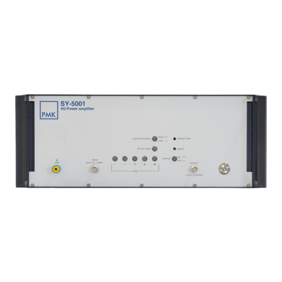
- Page 1 Probing Solutions. Made in Germany. SY-5000 SERIES 4-Quadrant Voltage Amplifier For Resistive And Inductive Loads SY-5001 | DC – 5 M Hz | 800 V /µs | ±150 V | ±10 A SY-5002 | DC – 7 M Hz | 450 V /µs | ±75 V | ±6 A...
-
Page 2: Table Of Contents
1 4 • Maximum Output Voltage | SY-5000 Series................• Low Signal Gain, Maximum Output Voltage | SY-5002.............. • Maximum Power Dissipation | SY-5002, Output Impedance | SY-5000 Series......Operation and Safety Concept......................Cooling Concept and Warm-up...................... -
Page 3: Manufacturer
(including damages for loss of profits, loss of business, loss of use or data, interruption of business and the like), even if PMK has been advised of the possibility of such damages arising from any defect or error in this manual or product. -
Page 4: Declaration Of Conformity
SY-5000 Series Declaration of Conformity PMK declares the conformity of this product with the actual required safety standards in accor- dance with the Low Voltage Directive (LVD) 2014/35/EU and EMC Directive 2014/30/EU: CEI/IEC 61010-1:2010 Safety requirements for electrical equipment for measurement,... -
Page 5: Safety Information
Only qualified personnel should use this instrument. Ground the instrument. The SY-5000 Series is a device of Protection Class I. In order to exclude the hazard of electric shocks, the device housing must be grounded and therefore always operated over the supplied three-conductor mains cable with protective ground conductor. Addi- tionaly a 4 mm ground socket (protective earth) is available at the front panel. -
Page 6: About 4-Quadrant Voltage Amplifiers
SY-5000 Series About 4-Quadrant Voltage Amplifiers The SY-5000 are linear, extremely wideband precision power amplifiers. They are ideal for all applications that require fast changing signals at any purely resistive and inductive loads. Two selectable operating voltages modes are available for high voltage/low current and low voltage/ high current applications. -
Page 7: Accessories Supplied
SY-5000 Series Accessories Supplied ● These operating instructions ● Power cable Maintenance ● Cleaning the device Wipe over the test device with a soft, moist cloth. Do not use any chemical cleaners. -
Page 8: Specifications
SY-5000 Series Specifications that are not marked as guaranteed are typical, valid Specifications after 30 minutes warm-up time, mains voltage: 230 V / 50 Hz. SY-5001 SY-5002 Input impedance 50 Ω ±2 % Input impedance 50 Ω ±2 % Gain 60 / 30 / 10 / 5 / 1 ±2 % (±100 ppm / °C) - Page 9 SY-5000 Series Specifications that are not marked as guaranteed are typical, valid Specifications after 30 minutes warm-up time, mains voltage: 230 V / 50 Hz. SY-5001 SY-5002 Power loss See graph ⁴ Switch back on after 10 s ³ See graph ⁴...
-
Page 10: Operating Elements - Front Panel, Back Panel
SY-5000 Series Operating Elements, SY-5001 Front Panel Elements: [1]: ON/OFF Switch to turn the amplifier from standby to „ON“ or back to standby. [2]: OUTPUT Power connector for output (±150V / ±10A max.). In „OFF“ state the output is switched to signal ground. - Page 11 SY-5000 Series Operating Elements, SY-5001 Back Panel Elements: [1]: GPIB CONNECTOR IEEE488-2 connector for remote interface. [2]: USB CONNECTOR TYPE B USB service interface for software updates, and for remote control. [3]: MAINS SWITCH All-pole mains switch for complete mains isolation of the instrument.
- Page 12 SY-5000 Series Operating Elements, SY-5002 Front Panel Elements: [1]: ON / OFF Switch to turn the amplifier from standby to „ON“ or back to standby. [2]: OUTPUT Switch to turn the output „ON“ or „OFF“. The switch lights up when the output is switched on.
- Page 13 SY-5000 Series Operating Elements, SY-5002 Back Panel Elements: [1]: Plug for non-heating apparatus with mains switch and fuseholder Fuse 4 AT (5x20 mm). All-pole mains switch for complete mains isolation of the amplifier. Socket for a C13 connector for mains supply.
-
Page 14: Graphs: Frequency And Temperature Dependent Behavior
SY-5000 Series Graphs: Frequency and Temperature Dependent Behavior S-5001 Maximum Power Dissipation, SY-5001 Maximum power dissipation per amplifier side Temperature [°C] Maximum Output Voltage, SY-5001 SY-5001 High Vp SY-5001 Low Vp 100k Frequency [Hz]... -
Page 15: Maximum Output Voltage | Sy-5000 Series
SY-5000 Series Maximum Output Voltage, SY-5002 SY-5002 High Vp SY-5002 Low Vp 100k Frequency [Hz]... -
Page 16: Low Signal Gain, Maximum Output Voltage | Sy-5002
SY-5000 Series Graphs: Frequency and Temperature Dependent Behavior SY-5002 Low Signal Gain, SY-5002 Network Analyser HP8751A (S.-No.: 3315J01756) PMK SY-5002, Low Signal Gain Input Signal: 100 mV, Load: 50 Ohm S11 / Ohm Frequency [Hz] Maximum Output Voltage, SY-5002 High Voltage Mode... -
Page 17: Maximum Power Dissipation | Sy-5002, Output Impedance | Sy-5000 Series
SY-5000 Series Maximum Power Dissipation, SY-5002 Temperature [°C] Output Impedance, SY-5000 Series High Voltage Mode Frequency [Hz]... -
Page 18: Operation And Safety Concept
SY-5000 Series Operation and Safety Concept SY-5000 series power amplifiers are equipped with various safety mechanisms in order to protect them- selves. If the amplifier self-protection is activated check your application setup, all connections and wiring. Cooling Concept and Warm-up Provide sufficient space behind and in front of the amplifier, that air can circulate through the device unobstructed. -
Page 19: Operational Startup
Overload and Overcurrent Protection The SY-5000 series has several partly interleaved safety mechanisms which protect the amplifier against overtemperature and overload. At a heat sink temperature of 70°C the amplifier switches off, the READY LED turns off and the PRO- TECTION LED lights up permanently. -
Page 20: Gain, Offset Zero And Output Voltage Ranges, Sy-5001
Each command is valid in its short form (capital letters) as well as in its long form. The commands are not case sensitive. Basic Commands *IDN? Query of device ID, e.g. „PMK, SY-5001, 18901980-0101, V1.6“. Operation Complete query returns „1“ after all previous commands are completely *OPC? executed. - Page 21 SY-5000 Series Input Subsystem Switch between gain factors. When switching from/to Gain = 60, INPut:GAIN 60|30|10|5|1 offset correction is carried out automatically. INPut:GAIN? Gain setting query, response: 60|30|10|5|1 INPut:OFFSet Offset correction is carried out. Output Subsystem Set shutdown threshold for short-circuit current detection (default 6.5 A). With OUTPut:CURRent:LIMit <5.5...15>...
- Page 22 SY-5000 Series SCPI Error Codes No error -100 Command error -101 Invalid character -102 Syntax error -103 Invalid separator -104 Data type error -108 Parameter not allowed -109 Missing parameter -120 Numeric data error -200 Executing error -221 Settings conflict...
- Page 23 SY-5000 Series Integration into Automated Test Systems, SY-5002 The USB interface is installed as a virtual COM port at 9600 baud, 8 data bits, 1 stop bit and no parity. The command frame consist of a length byte (entire frame) followed by an address byte.
-
Page 24: Remote Command Examples
SY-5000 Series Remote Command Examples • Frame: <length> <address> <command> <parameter> • Setting 50 Ω Input on (Amplifier address: 1) Command frame: 0x04 0x01 0x02 0x01 (all values are in hexadecimal notation) Response frame: 0x03 0x01 0x02 • Query Heatsink Temperature Command frame: 0x03 0x01 0x06 Response frame: 0x04 0x01 0x06 0x28 (e.g. - Page 25 SY-5000 Series Notes...
- Page 26 SY-5000 Series Notes...
- Page 27 SY-5000 Series Notes...
-
Page 28: Copyright, Revision
Copyright © 2021 PMK GmbH All rights reserved. Information in this publication supersedes that in all previously published material. Specifications are subject to change without notice. M-SY-5000 Revision 04.2021...
Need help?
Do you have a question about the SY-5000 Series and is the answer not in the manual?
Questions and answers