Table of Contents
Advertisement
Quick Links
Advertisement
Table of Contents

Summary of Contents for AESYS TC-430
- Page 1 TC-430 User manual Copyright © Aesys S.p.A. 2016-2018 All rights reserved...
- Page 2 - Added the description of RDMedia and 1.42.0-A 15/03/2017 NextStopMedia modes - Added keypad numeric mode 1.48.0-A 18/05/2017 - Added LCD screens features and diagnostics 1.50.0-A 09/06/2017 - Added HTTP interfaces description Copyright © 2016-2018 Aesys S.p.A. [ENG]TC-430_Manual_1_116_0_A.doc All rights reserved...
- Page 3 - Added CMS configuration & diagnostics - Added distance counters diagnostics - Added multimedia and PIS playlist switch - Updated HTTP interface specifications - Added cloud paired customer name 1.116.0-A 12/12/2018 Copyright © 2016-2018 Aesys S.p.A. [ENG]TC-430_Manual_1_116_0_A.doc All rights reserved...
-
Page 4: Table Of Contents
Destination override ......................43 7.3.4 P/R message during navigation ..................43 7.3.5 System diagnostics during navigation ................44 ROUTE/DESTINATION (MEDIA) MODE ............... 44 NEXTSTOP (MEDIA) MODE ................44 8. Diagnostics ........................ 45 Copyright © 2016-2018 Aesys S.p.A. [ENG]TC-430_Manual_1_116_0_A.doc All rights reserved... - Page 5 AUDIO SETUP ....................66 9.5.1 Local override ........................66 9.5.2 Muting ..........................67 9.5.3 Volume settings ........................ 68 9.5.4 External announcements delay ..................69 9.5.5 Announcements repetitions ....................70 SCREENS SETUP ..................... 71 Copyright © 2016-2018 Aesys S.p.A. [ENG]TC-430_Manual_1_116_0_A.doc All rights reserved...
- Page 6 Night mode ........................88 9.9.7 Keypad color ........................89 9.9.8 Keypad beep ........................90 9.9.9 Stop request: driver messages duration ................90 10. Administrative tasks ....................92 10.1 MAINTENANCE ....................92 Copyright © 2016-2018 Aesys S.p.A. [ENG]TC-430_Manual_1_116_0_A.doc All rights reserved...
- Page 7 11.7.1 Information about the system ..................103 11.7.2 Service data definition format ..................104 11.7.3 Navigation data format (EXT-MIS format) ..............104 11.8 SYSTEM REBOOT ..................106 12. References ....................... 108 Copyright © 2016-2018 Aesys S.p.A. [ENG]TC-430_Manual_1_116_0_A.doc All rights reserved...
- Page 8 Table 3: HAL™ connection icon ........................54 Table 4: Recognized filename extension for LED signs maintenance ............65 Table 5: Recognized labels for LED signs maintenance ................. 66 Table 6: HTTP interfaces summary ....................... 103 Copyright © 2016-2018 Aesys S.p.A. [ENG]TC-430_Manual_1_116_0_A.doc All rights reserved...
- Page 9 Figure 30: Dash sign message selection ......................34 Figure 31: “NextStop” main screen ........................34 Figure 32: Workshift selection ......................... 35 Figure 33: Service trip selection ........................35 Figure 34: Roadmap selection ......................... 36 Copyright © 2016-2018 Aesys S.p.A. [ENG]TC-430_Manual_1_116_0_A.doc All rights reserved...
- Page 10 Figure 68: Manual clock setup ......................... 59 Figure 69: Displays setup local override ......................59 Figure 70: LED signs brightness configuration ....................60 Figure 71: LED signs power saving ......................... 60 Copyright © 2016-2018 Aesys S.p.A. [ENG]TC-430_Manual_1_116_0_A.doc All rights reserved...
- Page 11 Figure 105: Configuration of J1708 codes length .................... 83 Figure 106: Configuration of J1708 dash sign command ................83 Figure 107: J1708 sniffer ..........................84 Figure 108: J1708 sniffer recording ......................... 84 Copyright © 2016-2018 Aesys S.p.A. [ENG]TC-430_Manual_1_116_0_A.doc All rights reserved...
- Page 12 Figure 134: Current data file storage folder selection ................... 100 Figure 135: Current data file storage filename selection ................101 Figure 136: Temporary message typing ......................101 Figure 137: Dirty words detection ........................102 Figure 138: Device reboot ..........................106 Copyright © 2016-2018 Aesys S.p.A. [ENG]TC-430_Manual_1_116_0_A.doc All rights reserved...
-
Page 13: Overview
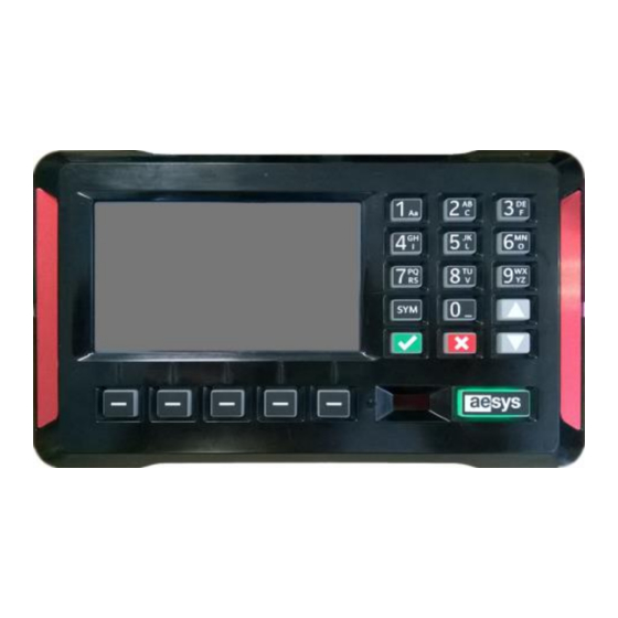
Pastrengo, 7/C – 24068 Seriate (Bergamo) 1. Overview Aesys® TC-430™ is the brand new on-board control unit to be used for managing Aesys® LED signs and vocal announcement equipments in “route/destination” mode. The control unit supports LED signs currently supported and it fully controllable by remote using Aesys®... -
Page 14: Keypad Usage
Arrow down Cancel Table 1: Keypad key functions While pressing a keypad key having several functions, then the set of accessible characters appears on the touch-screen (Figure 2). Figure 2: Keypad usage Copyright © 2016-2018 Aesys S.p.A. [ENG]TC-430_Manual_1_116_0_A.doc All rights reserved... - Page 15 ). Caps-lock can be toggled by holding the key for about one second. Some TC-430™ functions (also depending on configuration) may require the keypad to be turned in “numeric-only” mode. In this scenario the icon is shown in the status bar and the keypad can be used for typing digits only.
-
Page 16: Soft Keys Usage
Pastrengo, 7/C – 24068 Seriate (Bergamo) 3. Soft keys usage TC-430™ comes with 5 programmable “soft keys” whose functions depend on the context of the application. The current function of soft keys is shown in the bottom area of the touch-screen. -
Page 17: Menu Usage
Pastrengo, 7/C – 24068 Seriate (Bergamo) 4. Menu usage Some features of the TC-430™ control unit is accessible by the means on hierarchical menus. An example of a menu can be show by simply pressing “Menu” on the main screen (Figure 5). -
Page 18: System Messages
Pastrengo, 7/C – 24068 Seriate (Bergamo) 5. System messages TC-430™ reports the status of some operations by the means of system messages. A system message is a message that appears on the touch-screen and which may require some interaction with the control unit user. -
Page 19: System Status
TC-430™. The current data level and the current unit profile is available only if TC-430™ was loaded with a VDB file; if a TRX file was loaded instead only the label “TRX” is shown by the icon. -
Page 20: Basic Functions
Table 2: Status bar description 7. Basic functions The basic functions of the TC-430™ are presented in a slightly different way depending on the “system mode” (see paragraph 9.9.2 for further details about the mode). Paragraph 7.1 covers basic tasks which are common to all system modes, whereas paragraph 7.2 if referred to the “Route/destination”... - Page 21 [1] for further details about driver definition in Verba 2014™. Figure 10: Driver login Heading zeroes can be omitted while typing the driver code (so if the driver code is “000001” then simply “1” can be typed). Copyright © 2016-2018 Aesys S.p.A. [ENG]TC-430_Manual_1_116_0_A.doc All rights reserved...
-
Page 22: Data Loading
TC-430™ before operating the control unit on the road. The data file is produced by Aesys® Verba 2014™ (see [1] for further details about that) and can be either a VDB or a TRX file (the former being the preferred choice and the latter supported just for backward compatibility with old systems). -
Page 23: Media Loading
In lockout mode the LCD screen and the keyboard backlight is turned off and any further user interaction with the system is prevented; only the “Aesys” button remains active and its coloration turns to green, just to make clear that the system is in energy-saving mode (see Figure 13). -
Page 24: Service Idling
7.1.6 Media files selection TC-430™ can manage LCD screens connected to it via network. The configuration of available LCD screens is done by the means Verba 2014™ (refer to [1] for further info) and their list is made available to the control unit by uploading a proper data file (see paragraph 7.1.2). -
Page 25: Route/Destination Mode
Figure 15 shows the main screen of TC-430™ while in Route/destination mode: soft keys report the most important functions offered by the active mode (all remaining functions can be accessed via “Menu” button). - Page 26 If the destinations list is accessed from TC-430™ main screen by typing an alphanumeric character on the keypad, then the pressed key is taken as a part of the filter (considering the last filter mode selected by the user).
- Page 27 The current destination can be cleared by selecting “Clear” in destinations selection list. Alternatively the current destination can be cleared also by selecting “Menu Clear signs” or by pressing Service menu in the TC-430™ main screen). The screen in Figure 20 is shown. Copyright © 2016-2018 Aesys S.p.A. [ENG]TC-430_Manual_1_116_0_A.doc All rights reserved...
-
Page 28: Preferred Destinations
If no destination is currently selected then external LED signs are turned blank. 7.2.2 Preferred destinations TC-430™ allows the definition of a couple of destinations as the “preferred” destinations. The selection of preferred destinations is very quick and can be made by simply pressing the soft keys labeled “Dest A” and ... -
Page 29: Default Destination
Preferred destinations are stored as an association with some destinations contained in the current data file being used by the system. If a new data file is loaded into the system, then TC-430™ tries to preserve preferred destinations selection at its best, but may give up if saved preferred destinations are available no more in the new data file. -
Page 30: Inversions
An inversion is an association between two destinations, which tells that a destination is the opposite of the another one. Inversions definition is made using Aesys® Verba 2014™ [1] and it is stored in the data file being loaded by the control unit. -
Page 31: P/R Message
P/R messages (public relation messages) are intended for publication on external LED signs. External signs alternately show current destination (if any) and current P/R message (if any). The list of available P/R messages is accessed by selecting “P/R” from the TC-430™ main screen or by ... -
Page 32: Route Number
Figure 27: Current route selection The current route number can be cleared by simply typing an empty string. When the current route number if confirmed, then it is reported on the TC-430™ main screen (Figure 28). Copyright © 2016-2018 Aesys S.p.A. -
Page 33: Dash Sign Message
Figure 29: Dash sign message selection The dash sign message can be cleared by simply typing an empty string. When the dash sign message if confirmed, then it is reported on the TC-430™ main screen (Figure 30). Copyright © 2016-2018 Aesys S.p.A. -
Page 34: Nextstop Mode
Figure 30: Dash sign message selection NextStop mode While in NextStop, the TC-430™ is normally used for recognizing a given path or an entire service (a trip, a roadmap or a workshift). Figure 31 shows the main screen of TC-430™ while in NextStop mode: soft keys report the most important functions offered by the active mode (all remaining functions can be accessed via “Menu”... - Page 35 (Figure 39). Alternatively, the service to be executed can be represented by a roadmap. In such a case the selection is performed by pressing the “Roadmap” button on TC-430™ main screen or by selecting “Menu Service ...
- Page 36 Finally another way for selecting the service to be executed is represented by the direct selection of a single trip. The procedure is started by pressing “Trip” button on TC-430™ main screen or by selecting “Menu Service menu Select trip”.
-
Page 37: Navigation
(as it would happen driving a trip). 7.3.2 Navigation Once a service is selected (see paragraph 7.3.1) the TC-430™ screen is turned into navigation mode (Figure 39). During the navigation, the system autonomously command all the signs (external and/or internal) and all other on-board equipment depending on the service program defined in Verba 2014™... - Page 38 “Align”. When a stop different from the current one has been selected by the user, then the visualization can be reverted back to the current stop simply pressing the button “Current” (Figure 40). Copyright © 2016-2018 Aesys S.p.A. [ENG]TC-430_Manual_1_116_0_A.doc...
- Page 39 If the current time is compatible with the expected service time but the bus is not at the location of the service start terminus, then a banner reporting “Waiting terminus…” is reported on the screen (Figure 42). Copyright © 2016-2018 Aesys S.p.A. [ENG]TC-430_Manual_1_116_0_A.doc...
- Page 40 When the current trip is completed, the screen in Figure 44 is shown for some seconds: after that the subsequent trip in the current service (if any) is automatically commenced, otherwise the service is closed and the system returns to the main screen. Copyright © 2016-2018 Aesys S.p.A. [ENG]TC-430_Manual_1_116_0_A.doc All rights reserved...
- Page 41 The currently selected service can be abandoned at any time, pressing the button “Abort” (thus cancelling the execution of the selected service). A proper confirmation message is shown on screen before aborting the service (Figure 46). Copyright © 2016-2018 Aesys S.p.A. [ENG]TC-430_Manual_1_116_0_A.doc All rights reserved...
- Page 42 Figure 47: Multimedia files missing It's also possible to get the detailed list of the missing mutlimedia files by holding the button labelled “Missing” (Figure 48). Figure 48: Multimedia files missing (details) Copyright © 2016-2018 Aesys S.p.A. [ENG]TC-430_Manual_1_116_0_A.doc All rights reserved...
-
Page 43: Destination Override
P/R messages can be manually selected by the driver during navigation by pressing the button “P/R”. The list of available P/R messages is presented on screen for selection. When a P/R message is active, the button “P/R” is turned red (Figure 50). Copyright © 2016-2018 Aesys S.p.A. [ENG]TC-430_Manual_1_116_0_A.doc All rights reserved... -
Page 44: System Diagnostics During Navigation
The NextStop (media) mode is exactly the same same as NextStop mode (described in 7.3) except that media selection shortcut (see paragraph 7.1.6) in presented as soft key on the main screen instead of info message selection (see paragraph 7.2.5). Copyright © 2016-2018 Aesys S.p.A. [ENG]TC-430_Manual_1_116_0_A.doc All rights reserved... -
Page 45: Diagnostics
GPS settings, the version of the dirty words definition and the current timezone). Aesys® customer service can ask these info when providing assistance. By clicking the “Storage” button it is also possible to show a screen summarizing the current usage of mass storages available on the system (Figure 52). -
Page 46: Hardware Monitor
Stop request icons (standard and wheelchair request) turn red when the voltage is above 4.5V threshold (+/- 0.5V hysteresis). The threshold has been studied in order to conform to the majority of bus installations, but can anyway be configured to different values. Please contact Aesys® customer service if in need to change threshold and/or hysteresis figures. -
Page 47: Signs Diagnostics
(Figure 55). The problem can be fixed by simply implementing in Aesys® Verba 2014™ [1] the resources corresponding to the current sign publication. - Page 48 For every sign supporting self-diagnostic, the count of broken LEDs (absolute and percentage), the count of total sign LEDs and/or the version of the firmware running on the sign is reported. Copyright © 2016-2018 Aesys S.p.A. [ENG]TC-430_Manual_1_116_0_A.doc All rights reserved...
-
Page 49: Audio Devices Diagnostics
“M” the automatic muting time and “U” the automatic un-muting time). TTS vocal announcement equipments are labelled “TTS” or “BUILT-IN TTS” depending on the fact that the system is relying on an externeal device (namely an Aesys® DevonPro™ device) or to the internal TTS engine (if available). -
Page 50: Text-To-Speech (Tts) Diagnostics
The remaining part of the screen lists the voices currently available for the TTS engine (that is: voices that are enabled by the TTS certificate file and that have been properly configured within the TC-430™ configuration). For every voice, the paths to the LIB, VOX, lexicon and PLS file are reported, together with the MD5 digest of lexicon and PLS files). - Page 51 It is also possible to get detailed information about a screen (if supported by the device) by clicking on the correspondent line (Figure 60). Copyright © 2016-2018 Aesys S.p.A. [ENG]TC-430_Manual_1_116_0_A.doc All rights reserved...
-
Page 52: Gps Status
GPS fix is available, otherwise it is shown as Please be aware that the heading is updated only if the speed is not null (that is, only if the bus is moving). Copyright © 2016-2018 Aesys S.p.A. [ENG]TC-430_Manual_1_116_0_A.doc... -
Page 53: Networking Status
(the icon gets properly colorized in order to report the quality of the network signal). Server connection The diagnostic about the status of the connection toward Aesys® Verba 2014™ and/or toward Aesys® ... - Page 54 Figure 63: Server connection status Figure 63 reports the IP address and the UDP port the TC-430™ is trying to contact Verba 2014™ at on both wireless and 2G/3G interface, via external router (IP address and UDP ports are configured in Verba 2014™...
-
Page 55: Cms (Multimedia Contents)
“Menu CMS” (Figure 64) reports the current status of the control unit module Diagnostics menu devoted to synchronizing with Aesys® CMS for multimedia contents (configured as described in paragraph 9.8.7). Figure 64: CMS diagnostics The CMS mode and the URL of the CMS channel currently being synchronized on the control uniti is reported. - Page 56 (the conversion is continuously updated by the system as long as the bus travels at a relevant speed and the GPS fix is available). Copyright © 2016-2018 Aesys S.p.A. [ENG]TC-430_Manual_1_116_0_A.doc All rights reserved...
-
Page 57: System Configuration
Pastrengo, 7/C – 24068 Seriate (Bergamo) 9. System configuration TC-430™ configuration is accessed by entering the “Setup” menu (secondary function of the rightmost soft key on system main screen). Please consider that a part of system configuration can come with the current data file being used by the system. -
Page 58: Date/Time Setup
“Automatic timezone (from file)” for using the timezone specified in the data file being used by the system (please refer to [1] for directions about how it is possible to configure the timezone using Aesys® Verba 2014™). -
Page 59: Displays Setup
Displays setup Figure 69: Displays setup local override Changes are immediately applied (so there is no need to press any “Ok” button): simply press “Back” for confirming settings and exiting the menu. Copyright © 2016-2018 Aesys S.p.A. [ENG]TC-430_Manual_1_116_0_A.doc All rights reserved... -
Page 60: Signs Brightness
While a sign enters the power saving mode, then its publication is blanked (to save energy). Signs enter the power saving mode when a configurable amount of time has elapsed since bus engine switch-off (please Copyright © 2016-2018 Aesys S.p.A. [ENG]TC-430_Manual_1_116_0_A.doc... -
Page 61: Internal Signs Enabling
Pastrengo, 7/C – 24068 Seriate (Bergamo) refer to the installation manual of TC-430™ in order to have further info about cablings related to the bus engine status input signal, and refer to paragraph 9.6 for details about engine signal configuration). -
Page 62: Last Publications
Changes are immediately applied (so there is no need to press any “Ok” button): simply press “Back” for confirming settings and exiting the menu. 9.4.6 Last publications If signs local settings override is enabled (paragraph 9.4.1) then TC-430™ can be configured for automatically reloading the last used destination, P/R message of info message upon reboot. Such ... -
Page 63: Broken Leds Threshold
9.4.8 Broken LEDs threshold If signs being driven by TC-430™ support self-diagnostic and displays self-diagnostic is enabled (see paragraph 9.4.5) then the count of broken LEDs can be reported into the signs self-diagnostic status (see paragraph 8.3). -
Page 64: Displays Maintenance
ECHNOLOGIES via Pastrengo, 7/C – 24068 Seriate (Bergamo) 9.4.9 Displays maintenance It is possible to make use of TC-430™ control unit for updating the firmware, configuration or fonts of connected LED signs, such a functionality being available at “Setup... - Page 65 Maintenance baud rate”). Figure 79: “options.ini” example TC-430™ automatically tries to perform all the update tasks specified by the files available in the selected folder and then shows an update report at the end of the entire process. For backward compatibility with former Aesys® DC-600™ control units, the files in the selected folder can also be specified with the following naming schema: <AA><LBL>.DIS, where <AA>...
-
Page 66: Audio Setup
Sign fonts update (binary format) Table 5: Recognized labels for LED signs maintenance For backward compatibility also with former Aesys® KC-640™ control units, also the following file name schema is recognized: <AA><XXX>.<EXT>, where <AA> is the address of the target sign specified as two digits (being “01”... -
Page 67: Muting
(Figure 81). Figure 81: Vocal announcement equipments muting TC-430™ can also be configured in order to automatically mute vocal announcement equipments depending on current time. The feature is useful for avoiding to disturb citizenship at night (muting the buses external announcements performed at bus stops). -
Page 68: Volume Settings
If automatic mode is enabled, then the available volume range for automatic adjustment is configurable by accessing “Setup Set automatic volume range” (Figure 84) Audio setup Copyright © 2016-2018 Aesys S.p.A. [ENG]TC-430_Manual_1_116_0_A.doc All rights reserved... -
Page 69: External Announcements Delay
The delay to be obeyed by vocal announcement equipments can be configured by dragging the slider in Figure 85 on the touch-screen of by pressing “-” or “+” for respectively decreasing or increasing the delay amount. Copyright © 2016-2018 Aesys S.p.A. [ENG]TC-430_Manual_1_116_0_A.doc All rights reserved... -
Page 70: Announcements Repetitions
9.5.5 Announcements repetitions TC-430™ vocal announcements can be repeated several times (for letting the destination of the bus to be announced several times if the bus remains at the stop keeping doors open). ... -
Page 71: Screens Setup
If screens local settings override is enabled (paragraph 9.6.1) then the brightness of screens can be configured by accessing “Setup Brightness” (Figure 89). Screens setup Figure 89: Screens brightness configuration Copyright © 2016-2018 Aesys S.p.A. [ENG]TC-430_Manual_1_116_0_A.doc All rights reserved... -
Page 72: Screens Audio Volume
The screen at “Setup Media playlist switch” (Figure 91) can be used for selecting which Screens setup is the source of the multimedia playlist to be reproduced by Aesys® on-board LCD/TFT screens connected to the system. Options are: Media: the multimedia playlist reports the media files manually selected by the bus driver (paragraph 7.1.6);... -
Page 73: Pis Playlist Switch
The screen at “Setup PIS playlist switch” (Figure 92) can be used for selecting which is Screens setup the source of the passenger information (PIS) playlist to be reproduced by Aesys® on-board LCD/TFT screens connected to the system. Options are: MME package: the PIS playlist reports the media files referred by the MME package currently available on the system (paragraph 7.1.3);... -
Page 74: Interfaces Setup
9.8.1 Bus identification TC-430™ can connect via wireless network to Verba 2014™, in order to receive data definition files and/or commands issued by remote. For being Verba 2014™ able to identify any bus, it is requested that an unique code is assigned to each bus, corresponding to the buses base data programmed in Verba 2014™... -
Page 75: Cloud Setup
Figure 94: Bus identification code configuration 9.8.2 Cloud setup TC-430™ introduced the support to Aesys® cloud connection. Please notice that the support is still *EXPERIMENTAL* and it is not intended for productive environment (even because Aesys® cloud infrastructure has not been deployed to production too). -
Page 76: Wireless Settings Override
TC-430™ exploits a 802.11 b/g/n wireless network adapter in order to connect to other equipments (on- board and/or stationary). TC-430™ can connect to open networks or network protected by WEP (64 or 128 bits), WPA personal (WPA/PSK) or WPA2 Personal (WPA2/PSK). -
Page 77: Wireless Setup
9.8.5 Wireless setup If wireless settings override has been enabled (paragraph 9.8.4) then the wireless configuration can be modified by accessing “Setup Network interfaces Wireless setup”. Copyright © 2016-2018 Aesys S.p.A. [ENG]TC-430_Manual_1_116_0_A.doc All rights reserved... -
Page 78: External Router
9.8.6 External router Aesys® TC-430™ can be connected to central server through a router connected via Ethernet cable to the control unit. In such a scenario the external router is used *instead* of internal TC-430™ wireless adapter. -
Page 79: Cms
CMS can be adjuisted by accessing “Setup Interfaces setup CMS”. Note The description of Aesys® Creo™ goes far beyond the scope of this document; please refer to Aesys® customer service for more details about it. 9.8.7.1 Mode... -
Page 80: Cms Channel Url
ECHNOLOGIES via Pastrengo, 7/C – 24068 Seriate (Bergamo) Manual: the URL of the CMS is manually typed by an operator on TC-430® keypad (see paragraph 9.8.7.2); USB: a CMS channel has been uploaded to the control unit by the means of an USB key (see paragraph 7.1.3). -
Page 81: Protocol Kc-2S-U
Protocol version” (Figure 102) Figure 102: Protocol KC-2S-U version configuration 9.8.8.2 Internal sign type For allowing the TC-430™ to exploit some features of the KC-2S-U protocol the type of the internal sign (if any) has to be configure through “Setup... -
Page 82: Serial Baud-Rate
ECHNOLOGIES via Pastrengo, 7/C – 24068 Seriate (Bergamo) Figure 103: Protocol KC-2S-U internal sign type configuration Please refer to Aesys® customer service for further support about internal sign type configuration. 9.8.8.3 Serial baud-rate The baud-date being used by the KC-2S-U protocol while served over serial channel (RS-232 or RS-485) ... -
Page 83: Dash Sign Command
“Dest6/PR6/Route6” (6 characters for destination codes, 6 characters for P/R codes, 6 characters for route texts); “Dest4/PR4/Route3” (4 characters for destination codes, 4 characters for P/R codes, 3 characters for route texts). The latter option is the default one for retro-compatibility reasons (with respect to Aesys® KC-640 control units). 9.8.9.2 Dash sign command Dash sign (when enabled, see paragraph 9.4.5) can be handled through the J1708 interface by the means of... -
Page 84: J1708 Sniffer
Counters can be reset hitting the “Reset” button. The TC-430™ J1708 sniffer allows to “record” a trace of data exchanged on the J1708 bus. Hitting the button “Rec” the recording begins. While recording, a blinking warning label is shown on the screen and the right-most button is turned into “Stop”... -
Page 85: Control Unit
Pastrengo, 7/C – 24068 Seriate (Bergamo) Hitting “Stop” causes the recording to be stopped: TC-430™ ask for the path and the file name to store the trace to (an USB mass storage connected to the control unit is requested for complete this step): a default “.j1708”... -
Page 86: Route Management
9.9.3 Route management TC-430™ supports the legacy route management as well (as it was for Aesys® KC-640™ control unit). While route management is enforced by the control unit, the system tries to replace a sequence of given characters in the destination sign implementations with the number of the current route being handled by the system (the current route number can be typed by the driver or received from an external system). -
Page 87: Idling Time
9.9.4 Idling time TC-430™ goes to idle state after a configurable interval of time since the last interaction of the system user (keypad or touch-screen activity). While in idle mode the brightness of both the touch-screen and the keypad is dimmed (only if TC-430™ is not in administrative mode, that is only if TC-430™... -
Page 88: Touch-Screen And Keypad Brightness
9.9.6 Night mode Aesys® TC-430™ can be turned into night mode in order to greatly reduce the amount of light coming from the unit (e.g. during night travels). Night mode can be quickly toggled by pressing “Aesys” button on TC-430™ keypad. -
Page 89: Keypad Color
Pastrengo, 7/C – 24068 Seriate (Bergamo) Figure 115: Night mode 9.9.7 Keypad color TC-430™ manages a configurable keypad colorization which may differ from driver mode (the normal mode the system enters at start-up) and the administrative mode (accessed by the “Setup” menu). ... -
Page 90: Keypad Beep
9.9.9 Stop request: driver messages duration TC-430™ control unit can be configured in order to show some message to the driver for notifying the stop request (and also wheelchair stop request), as described in paragraph 11.3. - Page 91 The duration of stop request messages for the driver can also be retrieved from the current data file, simply by selecting “Auto”. Changes are immediately applied (so there is no need to press any “Ok” button): simply press “Back” for confirming settings and exiting menu. Copyright © 2016-2018 Aesys S.p.A. [ENG]TC-430_Manual_1_116_0_A.doc All rights reserved...
-
Page 92: Administrative Tasks
Figure 120 is shown for allowing the selection of the software upgrade file to be applied. Figure 120: Software upgrade file selection Software upgrades are usually shipped as “.tar.gz” files, but this might change (please refer to Aesys® technical support for having the latest software upgrades for TC-430™). -
Page 93: Firmware Upgrades
Be aware! Firmware upgrade is a critical operation: problems or errors occurring during the upgrade process might make TC-430™ unusable. Please pay attention and only apply firmware upgrades directly suggested by Aesys®. TC-430™ firmware can be upgraded selecting “Setup Load new firmware”. -
Page 94: Touch-Screen Recalibration
8.1). 10.1.3 Touch-screen recalibration TC-430™ is normally calibrated at the factory and no further maintenance should be necessary. Anyway if the touch-screen becomes somehow inaccurate it is possible to repeat the calibration again by simply ... -
Page 95: Factory Defaults
(5 points have to be tapped). Figure 126: Touch-screen calibration process At the end of the calibration process, TC-430™ software is automatically restarted. 10.1.4 Factory defaults TC-430™ factory defaults can be restored selecting “Setup ... -
Page 96: Serial Number Configuration
10.1.6 Log files saving The log files generated by the TC-430™, containing all the log messages, can be saved as a compressed archive (tar.gz) to an USB pen drive. The log files saving is started just connecting a USB key to the control ... -
Page 97: Miscellanous
ECHNOLOGIES via Pastrengo, 7/C – 24068 Seriate (Bergamo) After having selected the folder, just pressing the “Select” button, TC-430™ will show another screen asking for the desired file name. The screen in Figure 126 is shown. Figure 129: Type file name The saving on usb stick starts when the “Ok”... -
Page 98: Events Handling
430™ boot or the loading of a new data file). 11.2 Events handling TC-430™ can monitor the current status of bus doors and wheelchair lift, if available and if connected to the system. Please refer to TC-430™ installation and cabling documentation for further details about connections and refer to paragraph 9.6 for signals configuration. - Page 99 (icon next to current stop name) or manual navigation screens (icon next to current destination), as shown in Figure 133. Figure 133: Stop request reminders The reminder icon includes a wheelchair if the stop was requested for wheelchairs. Copyright © 2016-2018 Aesys S.p.A. [ENG]TC-430_Manual_1_116_0_A.doc All rights reserved...
-
Page 100: Emergency Handling
(paragraph 6. ) and normal LED signs publication is restored. 11.5 Data file storage It is possible to download the current data file from TC-430™ to a USB mass storage device (e.g. for copying the same exact destinations/messages database to another control unit). ... -
Page 101: Temporary Destination
Temporary destination publication is confirmed by pressing “Ok”. If a temporary destination is being shown by a LED sign, then the text “[TEMP]” appears in the description of LED sign current publication (see paragraph 8.3). Copyright © 2016-2018 Aesys S.p.A. [ENG]TC-430_Manual_1_116_0_A.doc All rights reserved... -
Page 102: Http Interfaces
Pastrengo, 7/C – 24068 Seriate (Bergamo) TC-430™ defines a configurable set of words (“dirty words”) which are forbidden to be typed in a temporary destination message. If one of those words is detected in the typed message, the publication is forbidden and the screen reported in Figure 137 is shown. -
Page 103: Information About The System
The status of the CMS module Table 6: HTTP interfaces summary 11.7.1 Information about the system The following data fragment represents the JSON document returned when asking info about the TC-430™ system (http://<tc-430-ipaddress>:<port>/system/info). Every item of the JSON document is commented for documenting its meaning. -
Page 104: Service Data Definition Format
Every item of the JSON document is commented for documenting its meaning. "format": "vdb", the format of the service data definition file being used by the TC-430™ (it can be none, trx or vdb) "level": 90, the current service data definition; -1 if the level is not available (e.g. - Page 105 "nm1": "Frejus - Stop 1", stop name in first language "nm2": "Stop 1" stop name in second language "id": "000LV2", "ix": 12, "nm1": "Frejus - Stop 2", "nm2": "Stop 2" Copyright © 2016-2018 Aesys S.p.A. [ENG]TC-430_Manual_1_116_0_A.doc All rights reserved...
-
Page 106: System Reboot
(info about the trip) "ver": 1 version of the data structure 11.8 System reboot TC-430™ can be simply rebooted by selecting “Menu Reboot” (Figure 138). Figure 138: Device reboot Copyright © 2016-2018 Aesys S.p.A. [ENG]TC-430_Manual_1_116_0_A.doc All rights reserved... - Page 107 OMMUNICATION AND ISUALIZATION ECHNOLOGIES via Pastrengo, 7/C – 24068 Seriate (Bergamo) “Reboot” will cause the operating system of TC-430™ to be rebooted (software-reset) while “Reset” will cause the system to be hardware-reset. Copyright © 2016-2018 Aesys S.p.A. [ENG]TC-430_Manual_1_116_0_A.doc All rights reserved...
-
Page 108: References
ECHNOLOGIES via Pastrengo, 7/C – 24068 Seriate (Bergamo) 12. References “Aesys® Verba 2014™ User Guide”, Aesys S.p.A. 2006 – 2018 “Aesys® KC-2S-U protocol version 1.0.0”, Aesys S.p.A. 2016 – 2018 “Aesys® HAL™ User Guide”, Aesys S.p.A. 2006 – 2018 Copyright © 2016-2018 Aesys S.p.A.