Advertisement
Quick Links
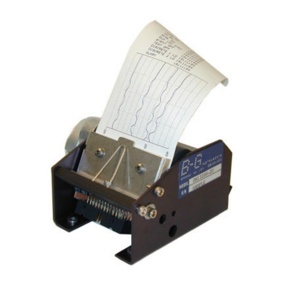
GENERAL DESCRIPTION
The DataPlot model PM1320 Print Mechanism incorporates a
fixed-dot thermal printhead with 320 heat element dots
arrayed in a single line across the width of the paper. The
mechanism holds a supply roll of thermal paper and causes
that paper to move past the printhead in steps of
approximately .005 inch. When driven by the DataPlot
CB1320 Printer Control Board, the print mechanism steps the
paper forward, pausing after each step to heat selected dots. In
this manner, a dot matrix representation of alphanumeric
and/or graphic data can be printed.
RESOLUTION
The 320 thermal dot elements are uniformly spaced 150 dots
per inch, or approximately .0067 inches apart. The total print
width is 2.13 inches, centered on the paper. The dot matrix
has a pitch, therefore, of .0067" across the width of the
paper by .005" along its length.
Technical Data and Instructions
DataPlot Print Mechanism
Model PM1320
CONTROL BOARD CONNECTION
This print mechanism is designed to operate properly and
reliably when driven by the B-G Instruments' DataPlot model
CB1320 Control Board or another board specifically
approved by B -G Instruments for that purpose. Attempting to
operate this print mechanism in any other way may cause
permanent damage to its components that would not be
covered by warranty. With all system power off, attach the
supplied ribbon cable between the 26-pin printhead connector
and connector J4 on the control board, being sure to observe
correct polarity by aligning the red dots on the connectors
with those on the cable cads. Also connect the 8-pin stepper
motor cable to connector J 1 on the control board. This
connector is keyed to facilitate correct polarity assembly.
Refer to the CB1320 data sheet for instructions for applying
power and operating the printer.
MOUNTING
The DataPlot model PM1320 print mechanism is designed to
be mounted to a horizontal support platform, as shown
here, using 6-32 screws.
Mating PEM nuts are set
into the print mechanism
chassis. (See the drawing
on the reverse side of this
sheet for mounting
dimensions.) Usually a
housing cover is provided
for appearance and to
protect the mechanism.
Such a cover must include a slot, positioned to permit the
paper to exit freely. Many cabinet designers also provide a
transparent tear-off bar to facilitate tearing the paper a short
distance away from the platen. This makes it easy to lift the
paper from the platen when printing resumes.
PAPER OUT, PAPER LOADING
A paper sensor in the PM1320 provides signals that are used
by the CB1320 Control Board to stop printing when the paper
runs out and to "autoload" a new paper roll. To load the
printer, be sure the power is on and insert the paper end into
the paper feed slot beneath the platen from the rear. Be sure
the sensitive side (outside on roll) is away from the platen.
When the paper is fully inserted, the platen will run, pulling
about 2 inches of paper through.
Page 1 of 2
Release A, March 15, 2000
Advertisement

Related Manuals for B-G Instruments PM1320

Summary of Contents for B-G Instruments PM1320
- Page 1 PAPER OUT, PAPER LOADING A paper sensor in the PM1320 provides signals that are used by the CB1320 Control Board to stop printing when the paper runs out and to “autoload” a new paper roll. To load the printer, be sure the power is on and insert the paper end into the paper feed slot beneath the platen from the rear.
- Page 2 PM1320 been modified in any way not specifically authorized by printer. It is available from B-G Instruments in cartons of 36 B-G Instruments, Inc., and rolls, or in larger quantities.
Need help?
Do you have a question about the PM1320 and is the answer not in the manual?
Questions and answers