Advertisement
Quick Links
ST 6100 terminals are integrated IsatData Pro communications terminals manufactured by ORBCOMM.
ORBCOMM distributes the terminals through Solution Providers who activate the terminal on the IsatData Pro
network. The terminals are available with side or bottom connectors.
This guide provides information required for a successful, reliable installation of the terminal on a vehicle, boat or
other platform. This guide does not address the terminal's commissioning procedures as these procedures vary
depending upon the Solution Provider and their specific application.
Required Tools
Installation of the terminal requires the following tools:
•
Drill and 5.5 mm drill bit
•
30 mm diameter hole punch or hole saw (bottom connector version only)
•
Screwdriver
•
Socket wrench set
Required Materials
Installing a terminal requires the following recommended materials. These materials do not ship with the
terminal because they differ for each installation.
•
Qty 4 - M4 (8-32) 18-8 stainless steel screws (length depends on mounting surface thickness)
•
Qty 4 - M4 (8-32) nuts with 18-8 stainless steel flat and lock washers
•
Waterproof sealing tape
•
Dielectric grease
•
Qty 1 - Custom cable provided by your Solution Provider
•
Mating connector kit (ST100030-001)
Cable
The Solution Provider may provide a custom cable to connect to the terminal. Contact your Solution Provider if
you did not receive a cable.
Record the Mobile ID
Each terminal has a unique serial number, termed a mobile ID, used by ORBCOMM to register it on the IsatData
Pro network. This is a 15-digit alphanumeric identifier in the format "NNNNNNNNSKYXXXX" The mobile ID is
located on the bottom of the terminal and on the shipping box. Record this number before the terminal is
mounted. You need it later for commissioning the terminal on the network.
Installation Steps
CAUTION
Select the Mounting Location
•
Mount the terminal where it has a clear view of the sky/satellite. For a mobile installation, this means that
it is preferable to install at the highest point on the vehicle or vessel where it has a clear view of the sky in
all directions.
R9015 Version 03
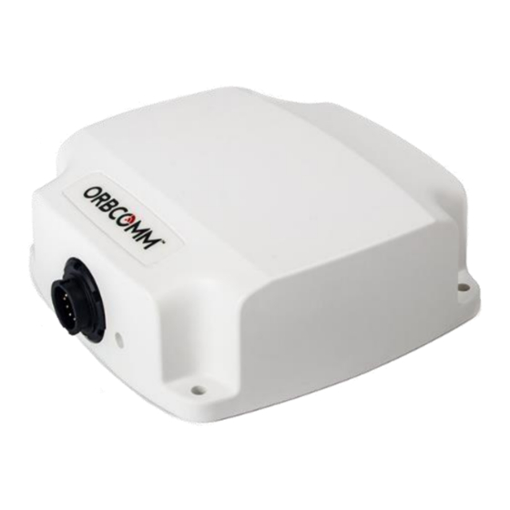
View of ST 6100 side connector
Most users install the terminals on a vehicle. It is very important for installers to
install the terminals in a safe and secure way to avoid danger or damage to
persons or property.
ST 6100 Terminal Installation Guide
1
© ORBCOMM
®
Proprietary
Advertisement

Related Manuals for ORBCOMM ST 6100


Summary of Contents for ORBCOMM ST 6100
- Page 1 Record the Mobile ID Each terminal has a unique serial number, termed a mobile ID, used by ORBCOMM to register it on the IsatData Pro network. This is a 15-digit alphanumeric identifier in the format "NNNNNNNNSKYXXXX" The mobile ID is located on the bottom of the terminal and on the shipping box.
- Page 2 This information is used later to set up the accelerometer service. Example: If the terminal is mounted horizontally on the vehicle roof such that the ORBCOMM logo is facing up and the cables are exiting towards the back of the driver, then record “top facing up and connectors facing back”.
- Page 3 ST 6100 Terminal Installation Guide • DO NOT mount the terminal close to air horns or any tractor roof hardware (for example, emergency lights) that could interfere with satellite communications. • DO NOT install the terminal inside the truck under the roof liner.
- Page 4 ST 6100 Terminal Installation Guide Tighten the cable connector with hand pressure by rotating the locking collar on the cable connector clockwise. Do not use a wrench. A tactile click is felt when the collar is properly engaged. Wipe off any extra grease around the connector and wrap the mating connector with waterproof sealing tape if using the connector in changing weather conditions.
- Page 5 ST 6100 Terminal Installation Guide Figure 8 Drill Template ST 6100 CAUTION Before drilling check the template against actual hardware for dimensional accuracy. If it is not correct, DO NOT USE THIS TEMPLATE. 101.6 mm (4.0 in) Ø 5.5 mm (7/32 in) 50.8 mm (2.0 in)
- Page 6 ST 6100 Terminal Installation Guide Cable Assembly Instructions This section provides the information necessary for the Solution Provider to assemble ST power/interface cables for the end-user. The mating connector kit (ST100030-001) does not ship with the terminal. The cable assembly procedures in this section are adequate for most installations. For particularly harsh environments such as maritime installations, use a cable with molded backfill as described in the Blunt Cut cable section later in this document.
- Page 7 ST 6100 Terminal Installation Guide Figure 10 Recommended Stripping Length Twist the ends tightly to prevent stranded wires from fraying. CAUTION Do not solder dip. Slide the following items over the cable in sequence and as shown in Figure 11: a sealing nut, a back shell and a coupling ring.
- Page 8 ST 6100 Terminal Installation Guide Using a soldering iron and solder, tin the wires and solder them to the connector solder cups (Figure 14) as per the proper pinout. Figure 14 Wires and Solder Cups Ensure the O-ring is in place over the connector body.
- Page 9 ST 6100 Terminal Installation Guide 10) Assemble the back shell to the connector body and wipe away any excess sealant. To aid in tightening the back shell, align the coupling ring key feature with the slot in the connector body (Figure 18).
- Page 10 ST 6100 Terminal Installation Guide Blunt Cut Cable This cable connects the ST terminal to external I/O lines and serial ports. There are 10 pins on this blunt cut cable; two connect the terminal to an RS-232 console serial port or an RS-485, four wires to connect to external I/O lines, and one each for ground and voltage.
- Page 11 ST 6100 Terminal Installation Guide Figure 22 Raw Cable Details 4 x I/O Overall Shield Aluminum Foil I/O Shield Aluminum Foil Outer Shield Drain 2 x RS-485 Twisted Pair PVC Jacket Black, UV Stable I/O Drain Power/Ground 2 x RS-232 www.ORBCOMM.com...
Need help?
Do you have a question about the ST 6100 and is the answer not in the manual?
Questions and answers