Advertisement
Quick Links
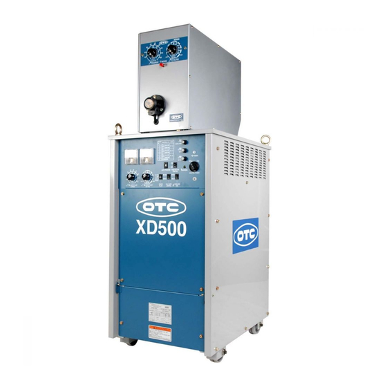
SERVICE MANUAL
DAIHEN DC arc welding power source
CO
/MAG
2
NOTE: Ther is a case that contents of thes service
munual is different from the latest information by
revision after product shipment. Use the owner's
manual of this procuct together.
DAIHEN Corporation
DYNA AUTO
350/500
CPXD- 350
CPXD- 500
WELDING PRODUCTION DIVISION
Service Manual No.C0056-1
C0056
C0052
Aug.11.2006
Advertisement

Subscribe to Our Youtube Channel
Related Manuals for Daihen OTC XD350


Summary of Contents for Daihen OTC XD350
- Page 1 Service Manual No.C0056-1 SERVICE MANUAL DAIHEN DC arc welding power source DYNA AUTO /MAG 350/500 CPXD- 350 C0056 CPXD- 500 C0052 NOTE: Ther is a case that contents of thes service munual is different from the latest information by revision after product shipment. Use the owner’s manual of this procuct together.
- Page 2 CPXD-350,500 SERVICE MANUAL 1. Caution in maintenance 1.1 To avoid electric shock and accident When checking internal power source, turn off the primary side of line disconnect switch and the control power source switch, wait more than 3 minuets and check that the built-in cooling fan stops completely then carry out checking.
- Page 3 CPXD-350,500 SERVICE MANUAL 1. Caution in maintenance (continued) 1.3 Handling of main circuit component (1) When attaching thyristor module to heat sink, apply micro computer and fix by designated torque. (2) Use torque of specific value also to clamp terminal. 1.4 In case of insulation resistance test When measuring insulation resistance and testing withstand voltage, follow the steps below.
- Page 4 CPXD-350,500 SERVICE MANUAL 2. Function of each printed circuit board 2.1 Function of printed circuit board and mounting position Printed circuit board Function Mounting position PART No. Fan frame ・Microcomputer control C0056P (CPXD-350) Sequence control (CPXD-350) Constant voltage control Chassis Welding control C0052P (CPXD-500)
- Page 5 CPXD-350,500 SERVICE MANUAL 2. Function of each printed circuit board (continued) 2.2 Operation of check terminal on printed circuit board T : is measured by tester S : is measured by oscilloscope 2.2.1 Check terminal on printed circuit board PC0056P Signal name Explanation Ground...
- Page 6 CPXD-350,500 SERVICE MANUAL 2. Function of each printed circuit board (continued) 2.2 Operation of check terminal on printed circuit board (continued) 2.2.2 Check terminal on printed circuit board C0045Q Signal name Explanation Ground T: CH1-, CH2+ +15V -15V T: CH1+, CH3- +15V +15V T: CH1-, CH4+...
- Page 7 CPXD-350,500 SERVICE MANUAL 2. Function of each printed circuit board (continued) 2.3 Adjustment resistance of printed circuit board and meaning of jumper switch. Adjustment resistance of printed circuit board C0056P Signal name Explanation Pre-flow time Adjust pre-flow time. Normal position is full of turning left. Post-flow time Adjust post-flow time.
- Page 8 CPXD-350,500 SERVICE MANUAL 2. Function of each printed circuit board (continued) 2.3 Adjustment resistance of printed circuit board and meaning of jumper switch (continued) Adjustment resistance of printed circuit board C0045Q Signal name Explanation Max. feed speed Mode1, current knob is Max. position and connecting with CM-2302: adjustment 170 rpm (Setting is done at the shipment) Jumper switch of printed circuit board C0045Q...
- Page 9 CPXD-350,500 SERVICE MANUAL 2. Function of each printed circuit board (continued) 2.4 Check point position of each printed circuit board 2.4.1 C0056P C0056P - 8 -...
- Page 10 CPXD-350,500 SERVICE MANUAL 2. Function of each printed circuit board (continued) 2.4 Check point position of each printed circuit board (continued) 2.4.2 C0045Q - 9 -...
- Page 11 CPXD-350,500 SERVICE MANUAL 2. Function of each printed circuit board (continued) 2.4 Check point position of each printed circuit board (continued) 2.4.3 P10174X - 10 -...
- Page 12 CPXD-350,500 SERVICE MANUAL 3. Troubleshooting 3.1 WARNING lamp When an error occurs, warning lamps on the front panel LED turns on or flashes, then the welding power source automatically stops. In this case, check the errors distinction by LED is possible. ●:OFF, ○:Light, ◎:Flash, △:Flash two times Error Front panel...
- Page 13 CPXD-350,500 SERVICE MANUAL 3. Troubleshooting (continued) 3.1 WARNING lamp (continued) ⑥ Error before starting welding machine When the CONTROL POWER switch is turned on while the TORCH switch is on, the warning lamp flashes (Flash 1) and the welding power source keep stopping. Turn off the TORCH switch to cancel the error.
- Page 14 CPXD-350,500 SERVICE MANUAL 3. Troubleshooting (continued) 3.2 Check of main circuit parts When check of main circuit parts, be caution “1.1 To avoid electric shock and accident” in particular. And resistance value in the list is changed by internal resistance of tester (digital tester in particular) that is used.
- Page 15 CPXD-350,500 SERVICE MANUAL 3. Troubleshooting (continued) 3.3 Welding error table Error Cause Checkpoint No arc is generated. No voltage applied between Complete connection of base metal and torch cable. torch and base metal. Fuse of input power disconnect switch. Complete connection of input cables.
-
Page 16: Control Power
CPXD-350,500 SERVICE MANUAL 3. Troubleshooting (continued) 3.4 Troubleshooting Trouble Cause Solution Main POWER lamp PL1 Fan FM rotates Trouble of PL1 lamp. Check the PL1. will not light. when CONTROL POWER switch S1 turns on. Fan FM will not Line disconnect switch (or Check power box. - Page 17 CPXD-350,500 SERVICE MANUAL 3.4 Troubleshooting (continued) Trouble Cause Solution Wire will not When pressing the Breaking of control cable of After checking cable and be fed when Inching switch, wire will wire feeder or poor contact of receptacle (line of feed motor), the torch not be fed.
- Page 18 CPXD-350,500 SERVICE MANUAL 4. Block diagram - 17 -...
- Page 19 CPXD-350,500 SERVICE MANUAL 5. Correspondence for user needs expect for a standard 5.1 Using initial current control Initial current control is “OFF” at the shipment but it becomes usable by turning C0056P (C0052P) S1 No.2 to “ON”. 0.37sec. 0.53sec. 5.2 Changing pre-flow time (For CO /MAG) 0.21sec.
- Page 20 CPXD-350,500 SERVICE MANUAL 5. Correspondence for user needs expect for a standard (continued) Shorter 5.5 Changing anti-stick time Longer Anti-stick time is 0.3~0.5 sec. at the shipment but it becomes usable to adjust time by R15 on C0056P. Arti-stick time regulation Anti-stick time is changed by welding method, wire diameter and current setting.
- Page 21 CPXD-350,500 SERVICE MANUAL 5. Correspondence for user needs expect for a standard (continued) 5.9 Using arc spot timer Arc spot timer SCT-31 1. Remove the bolts fastening the upper cover of the welding power source to open the cover. Connectors for arc spot timer is located close to 4P terminal board on fan frame. 2.
- Page 22 CPXD-350,500 SERVICE MANUAL 5. Correspondence for user needs expect for a standard (continued) 5.10 Connection between internal terminals and an automatic machine 4P terminal board mounted on a fan frame, which is used for connection to an automatic machine, is located inside the upper cover of the welding power source. And also, when external connection cables are led in, let the cables through a grommet with film located at the rear side of the welding machine.
- Page 23 CPXD-350,500 SERVICE MANUAL 6. Schematic diagram and parts layout 6.1 Schematic diagram for CPXD-350 - 22 -...
- Page 24 CPXD-350,500 SERVICE MANUAL 6. Schmatic diagram and parts layout (continued) 6.2 Schematic diagram for CPXD-500 - 23 -...
- Page 25 CPXD-350,500 SERVICE MANUAL 6. Schmatic diagram and parts layout (continued) 6.3 Parts layout for CPXD-350 for PCB2 CN16 (CASE GROUND) for PCB2 CN23 for PCB2 CN24 CON3 for PCB2 CN14 for CON4 LOWER (2A) for PCB2 CN25 for PCB2 CN19 for PCB1 CN6 HEATSINK -...
-
Page 26: Front Panel
CPXD-350,500 SERVICE MANUAL 6. Schmatic diagram and parts layout (continued) 6.3 Parts layout for CPXD-350 (continued) UPPER REAR SIDE CN9 CN10 CN11 CN12 CN13 CN14 CN15 PCB1 CN11 CN10 PCB2 TM 1 CN F M CN3A CN3B PCB3 SCR3 CN27 CN26 CN25 CN1A... - Page 27 CPXD-350,500 SERVICE MANUAL 6. Schmatic diagram and parts layout (continued) 6.4 Parts layout for CPXD-500 PCB2 HEATSINK (CASE GROUND) CN25 LOWER THP1 for PCB2 CN14 for PCB2 CN24 PCB1 CN6 for PCB2 CN19 for CON4 - SCR1 CON3 for PCB2 CN16 UPPER AC100V L2...
- Page 28 CPXD-350,500 SERVICE MANUAL 6. Schmatic diagram and parts layout (continued) 6.4 Parts layout for CPXD-500 (continued) FAN FLAME、SCR2、MS、FRONT PANEL CN25 CN26 CN27 PCB1 PCB2 CN3A CN3B CN14 CN12 CN15 CN13 CN11 CN10 HEATSINK(SCR1,THP1)、 CON1,2 T1、 THP2 CON3、R1、CT PCB3 CN1A CN1B SCR3 (CASE GROUND) CHASSIS...
- Page 29 CPXD-350,500 SERVICE MANUAL 7. Parts list Contact your local dealer to order parts. (See the back cover for telephone and fax numbers, and mailing address) Q’ty Parts No. Description Specifications Location Symbol XD350 XD500 C0049B00 C0049B00 3-phase transformer On side frame C0053B00 C0053B00 L1, L2...
- Page 30 CPXD-350,500 SERVICE MANUAL 7. Parts list (continued) Q’ty Parts No. Description Specifications Location Symbol XD350 XD500 THP2 4258-016 Thermostat US-602AXTTL 120˚C On DC reactor 4406-017 Hole current detector L03S400D15 On output terminal board 4509-821 Resistor 40SH 100ΩKA 4509-805 Resistor 40SH 1ΩKA On Chassis C2,3 4517-401...
- Page 31 CPXD-350,500 SERVICE MANUAL 8. Supplement This is not a guarantee value. Use as reference data. ●Setting of one-knob Welding voltage is output voltage when center of one-knob. (A real value changes by ejector) Flax cored (FCW) is XD500. Value is not changed if turning current knob to right more the point of Max. time to rotate (170 / 212rpm).
- Page 32 CPXD-350,500 SERVICE MANUAL 8. Supplement (continued) Current setting (A) Mode Setting Speed (rpm) Welding voltage 1.2mm Speed (rpm) Welding voltage 1.2mm Speed (rpm) Welding voltage 1.2mm Speed (rpm) Welding voltage 1.2mm Speed (rpm) Welding voltage 1.4mm Speed (rpm) Welding voltage 1.4mm Speed (rpm) Welding voltage...
- Page 33 CPXD-350,500 SERVICE MANUAL 9. Standard of current and voltage setting signal When carrying out to control output current and voltage by outside connection, refer to the order voltage in the below as standard. Input range of order voltage is between DC0~15V. Check the direction of CN1 and CN3 on P10174X is “B”...
- Page 34 CPXD-350,500 SERVICE MANUAL 10. Outside characteristics CPXD-350 The following data are things by the condition below. Input voltage: 200V Frequency: 60Hz Mode: CO solid, 1.2mm, Voltage individually adjustment Standard voltage Standard voltage Standard voltage Standard voltage Standard voltage 2V 3V 4V...
- Page 35 CPXD-350,500 SERVICE MANUAL 10. Outside characteristics CPXD-500 The following data are things by the condition below. Input voltage: 200V Frequency: 60Hz Mode: CO solid, 1.2mm, Voltage individually adjustment Standard voltage Standard voltage Standard voltage Standard voltage Standard voltage 1V 2V 3V...
Need help?
Do you have a question about the OTC XD350 and is the answer not in the manual?
Questions and answers