Table of Contents
Advertisement
Quick Links
INSTRUCTION MANUAL
Matsushima signal Conditioner
※The operator should read this Instruction Manual carefully and
handle the device correctly.
1-8-18 Norimatsu-Higashi,Yahatanishi-ku,Kitakyushu 807-0837 Japan
Phone No.(8193)691-3731 Fax No.(8193)691-3735
http://www.matsushima-m-tech.com
E-mail sales@matsushima-m-tech.com
FOR
TYPE
MSC-01
-0-
TMSC-001E
Rev2:Dec.19,2017
Advertisement
Table of Contents

Summary of Contents for Matsushima MSC-01
- Page 1 TMSC-001E Rev2:Dec.19,2017 INSTRUCTION MANUAL Matsushima signal Conditioner TYPE MSC-01 ※The operator should read this Instruction Manual carefully and handle the device correctly. 1-8-18 Norimatsu-Higashi,Yahatanishi-ku,Kitakyushu 807-0837 Japan Phone No.(8193)691-3731 Fax No.(8193)691-3735 http://www.matsushima-m-tech.com E-mail sales@matsushima-m-tech.com -0-...
-
Page 2: Table Of Contents
Table of Contents Page Table of Contents ・・・・・・・・・・・・・・・・・・・・・・ Safety Precautions ・・・・・・・・・・・・・・・・・・・・・・ Overview ・・・・・・・・・・・・・・・・・・・・・・・・・ 1. Specifications ・・・・・・・・・・・・・・・・・・・・・・・・ 2. External Dimensions 3. ・・・・・・・・・・・・・・・・・・・・・ Names of Parts 4. ・・・・・・・・・・・・・・・・・・・・・・・・ Installation Method 5. ・・・・・・・・・・・・・・・・・・・・・・ 5- 1. Installation Method ・・・・・・・・・・・・・・・・・・・・ 5- 2. Remove Method ・・・・・・・・・・・・・・・・・・・・・・ Connection Method 6. - Page 3 Also any loss induced by failure or malfunction of the equipment is not covered by this warranty. Failure or malfunction caused by following are not covered by this warranty: a. Modification or repair by a party other than MATSUSHIMA’s authorized personnel, or replacement of parts not recommended by MATSUSHIMA.
-
Page 4: Installation Method
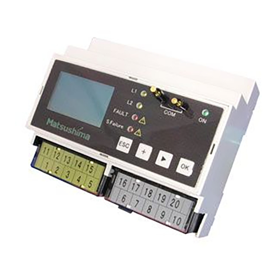
1.Overview MSC-01 is used in combination with one two-wire transmitter or 4 - 20 mA DC current output device. This product outputs the instrumentation signal and contact signal of 4 - 20 mA DC or 1 - 5 V DC corresponding to the input current signal. - Page 5 3.External Dimensions ( Schematic Diagram ) Unit : mm 【Inch】 (106)【4.1732】 (58)【2.2835】 DIN-Rail 20-M3 terminal screw Fig.1.Product external dimensions 4.Names of Parts HART sensor connection terminal Power LED(Green) Main unit Limit LED(Yellow) Equipment error LED(Red) Sensor error LED(Red) Operation button display screen Fixing screw of terminal (M3)
-
Page 6: Terminal Layout
5.Installation Method ※ In an environment with a lot of dust, metal powder, etc., place the product in a dust-proof case and take heat radiation measures. ※ Avoid vibrations and impacts as much as possible, since they may cause failures. ※... -
Page 7: Connection Terminal
6-2.Connection Terminal (※2) (※2) (※1) (※1) L N - - + - + + Power source Equipment failure Sensor failure Input signal(※3) No.1 Limit No.2 Limit Output signal (※4) 85~264V AC Relay output Relay output 10-20:2-wire sensor Relay output Relay output 17-18:3~24mA DC 9-20:analogue signal 17-19:0.75~6V DC... -
Page 8: Block Diagram
6-4.Block Diagram Analog Current Isolated circuit input circuit Output circuit Microcomputer + + Voltage output 2-wire Sensor + Output signal Current output Conditioning circuit - Current input - - Contact Output circuit No.2 Limit Button operation Relay No.2 Limit contact No.1 Limit LED (Display) Relay... -
Page 9: Warming-Up Operation And Start-Up Flow
7.Start-up 7-1.Warming-up Operation and Start-up Flow To stabilize the output signal, the equipment needs to be warmed up for at least 10 minutes after power-on. The start-up flow is shown in Figure 9. Mount the converter Execute the wiring Check the wiring Check the power supply Turn on the power Check that no error... -
Page 10: Lcd Screen And Button Operations
7-2.LCD Screen and Button Operational Perform the adjustment on the LCD screen using the operation buttons on the front panel. Operation buttons LCD screen (measuring screen) Menu display Item display 2 5 . 0 Button Operation Cancel of setting Unit display Error display Back to the previous Measurement value display... - Page 11 8.Settings and Functions The settings and hierarchy are shown in Figure 11. Menu=0 Menu=1 Menu=1-1 Menu=1-1-1 Menu Basic setup Display Displayed unit Measuring Screen Menu=1-1-2 Decimal point Menu=1-1-3 (Operation buttons and menu Scaling navigation Menu=1-2 Menu=1-2-1 Relay output No.1 Limit Menu=1-2-2 No.2 Limit +...
- Page 12 8-1.Display Unit Setting【Menu:1-1-1】 The item selects and sets the display unit. range:%, ton, m, ft, Pa, kPa MPa, bar, kgf/cm2, psi, mg/m3, µg/m3 Selection m3/h, ft3/h, t/h, kg/h, lb/h, mL/s, °C, °F, mA,blank (default value:%) (Measuring screen) 5 0.0 % O K ×1 Displayed unit 1-1-1...
- Page 13 8-2.Decimal Point Position Setting【Menu:1-1-2】 This item sets the decimal point position of the scale display value. Range of the decimal point position: No decimal point (00000.) - three decimal places (0.000) (default value: one decimal place 0000.0) * Note that, if you change the decimal point position after the scaling setting [section 8-3.], the decimal point position of the scaling setting value would be changed.
-
Page 14: Scaling Setting
8-3.Scaling Setting【Menu:1-1-3】 This item sets the values displayed when 4mA and 20mA are input into the equipment. Selection range: -99999 ~ + 99999 ( default value: 4mA = 0.0, 20mA = 100.0 ) (Measuring screen) 5 0.0 % A blinking indicates the item to be set. -
Page 15: 1 Limit Setting
8-4.No.1 Limit Setting【Menu:1-2-1】 This item sets the contact output operation point ( ON / OFF point ) of the No.1 Limit by %. 4mA and 20mA input signals correspond to 0% and 100% respectively. The set minimum hysteresis for ON and OFF points is 0.1%. Setting range : 0.0 ~... - Page 16 8-5.No.2 Limit Setting【Menu:1-2-2】 This item sets the contact output operation point ( ON / OFF point ) of the No.2 Limit by %. 4mA and 20mA input signals correspond to 0% and 100% respectively. The set minimum hysteresis for ON and OFF points is 0.1%. Setting range : 0.0 ~...
- Page 17 8-6.Sonsor Failure Relay Setting【Menu:1-2-3】 This item selects the sensor failure relay operation (active / inactive) when the error signal identified in 5-9 “Failure Setup. In” is input. Selection range : Execution / Non – Execution ( default value : Execution ) *For example, the setting is changed to "Non - Execution".
- Page 18 8-7.Sonsor Failure Mode Setting【Menu:1-3, 1-3-3】 This item selects how to output the analog output when an error input signal identified in 5-9 “Failure Setup. In” is input into the sensor. Selection range : Raw mode / Hold mode / Setting value ( default value : Raw mode ) Setting range of “Setting value”...
-
Page 19: Damping Setting
8-8.Damping Setting【Menu:1-4】 This item specifies the time constant (processing time until the output value reaches 63.2% of the normal output value (100%)). See Figure 12. When the time constant is set, the normal output value forms a curve shown in Figure 12. If the input/output signal is fluctuated, you can increase the setting value to increase the processing time taken to reach the normal output value, so that the fluctuation of the output signal is suppressed. -
Page 20: Failure Setup. In Setting
8-9.Failure Setup. In Setting【Menu:1-5】 This item sets the signal level used for recognizing the input signal as error signal. The upper and lower limits should be set. ・For the upper limit, if a signal higher than the setting value is input, the signal is recognized as error signal. ・For the lower limit, if a signal lower than the setting value is input, the signal is recognized as error signal. - Page 21 8-10.Analog Output Setting ( Test )【Menu:2-1】 This item is used to simulate an analog output independently of the input signal from the sensor. ( signal loop check, etc. ) Setting range: 3.0 – 24.0 mA [0.75 – 6.00 V] ( default value: 3.0 mA [ 0.75 V ] ) (Measuring screen) Analog output test Output value...
- Page 22 8-11.No.1 Relay Output Setting ( Test )【Menu:2-2-1】 The item is used to simulate an operation of the Limit 1 contact independently of the input signal from the sensor. (Measuring screen) Relay output (Test) *For example, ▶ 1. No.1 Limit a No.1 Limit output 2.
- Page 23 8-12.No.2 Relay Output Setting ( Test )【Menu:2-2-2】 The item is used to simulate an operation of the Limit 2 contact independently of the input signal from the sensor. (Measuring screen) Relay output (Test) 1. No.1 Limit ▶ 2. No.2 Limit 5 0.0 3.
- Page 24 8-13.Equipment Failure Output Setting ( Test )【Menu:2-2-3】 This is used to simulate an operation of the equipment failure contact. (Measuring screen) Relay output (Test) 1. No.1 Limit 2. No.2 Limit 5 0.0 ▶ 3. FAULT % 4. Sensor failure O K ×1 O K ×1 Menu ▶...
- Page 25 8-14.Sensor Failure Relay Output Setting ( Test )【Menu:2-2-4】 This is used to simulate an operation of the sensor failure contact independently of the input signal from the sensor. (Measuring screen) Relay output (Test) 1. No.1 Limit 2. No.2 Limit 5 0.0 3.
-
Page 26: Parameter Reset
8-15.Parameter Reset【Menu:3-1】 This item resets the setting values other than “Language” to the default values. (Measuring screen) Parameter reset 5 0.0 Parameter reset % ▶ Reset now ? O K ×1 Menu O K ×1 ( Reset is performed ) ▶... - Page 27 8-16.Factory Reset【Menu:3-2】 This item is used to reset all setting values including “Language” to the default values. (Measuring screen) Password Please enter the 6-digit password 5 0.0 % 1 0 0 0 0 O K ×1 O K ×1 Menu ▶...
- Page 28 8-17.Language Setting【Menu:4】 This item set the language used on the LCD screen to Japanese or English. Selection range : Japanese / English ( default value: Japanese ) (Measuring screen) ゲンゴセンタク 5 0.0 ヒョウジゲンゴ % ▶ *ニホンゴ エイゴ O K ×1 ( Use ESC button to return ESC ×2 Menu...
- Page 29 8-18.Device information【Menu:5】 This item displays the “revision” of the equipment. (Measuring screen) 5 0.0 % O K ×1 Menu ▶ 1. Basic setup 2. Test 3. Reset 4. Language 5. Device info + ×4 Menu 1. Basic setup 2. Test 3.
- Page 30 9.Standard Factory Setting Table 3. Standard Factory Setting Item Description Setting value Select the unit to be displayed on LCD Display unit 「%」「ton」「m」「ft」「Pa」「kPa」「MPa」「bar」 % 「kgf/cm2」「psi」「mg/m3」「µg/m3」「m3/h」 ( Menu:1-1-1 ) 「ft3/h」「t/h」「kg/h」「lb/h」「mL/s」「°C」「°F」 「mA」「blank」 Decimal point Set the decimal point of the value displayed XXXX.X...
-
Page 31: Troubleshooting
If one of the error codes shown in Table 4 is displayed, check the items described in the table before judging it as failure. This product is shipped after strict internal inspection. However, if any failure occurs due to manufacturing defect or accident during transportation, please contact MATSUSHIMA's person in charge of sales. Table 4. Troubleshooting Code...
Need help?
Do you have a question about the MSC-01 and is the answer not in the manual?
Questions and answers