Table of Contents
Advertisement
Quick Links
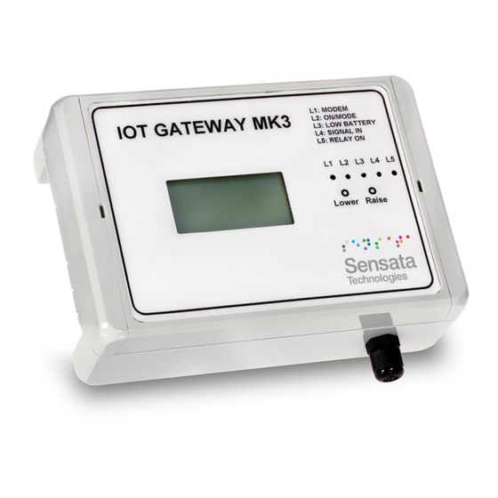
| IoT-Gateway-00 SERIES
12-24V DC POWERED OPERATING MANUAL
Whilst every effort has been taken to ensure the accuracy of this document, we accept no responsibility
for damage, injury, loss or expense resulting from errors or omissions, and reserve the right of amendment
Information for users
This equipment has been tested and found to comply with the limits for a Class B device, pursuant to part
15 of the FCC Rules. These limits are designed to provide reasonable protection against harmful
interference in a residential installation. This equipment generates uses and can radiate radio frequency
energy, and if not installed and used in accordance with the instructions, may cause harmful interference
to radio communications. However, there is no guarantee that interference will not occur in a particular
installation. If this equipment does cause harmful interference to radio or television reception, which can
be determined by turning the equipment off and on, the user is encouraged to try to correct the
Reorient or relocate the receiving antenna
•
•
Increase the separation between the equipment and receiver
Connect the equipment into an outlet on a circuit different to that which the receiver is connected
•
Consult the dealer or an experienced radio/TV technician for help
•
Caution: To satisfy FCC RF Exposure requirements for mobile and base station transmission
devices, a separation distance of 20cm or more should be maintained between the antenna of this
device and persons during operation. To ensure compliance operation at closer than this distance
is not recommended. The antenna used for this transmitter must not be co-located or operating in
conjunction with any other antenna or transmitter. No other antenna may be used with this
equipment other than the PCB antenna supplied with this equipment.
This document may not be reproduced in any way without the prior written permission of the company.
7 Cobham Road, Ferndown Industrial Estate, Wimborne
Tel: +44(0)1202 897969, email: sales@cynergy3.com
opyright © 2021 Sensata Technologies, Inc.
C
|IoT-Gateway-00
12-24V DC POWERED
IoT-Gateway
without notice.
interference by one or more of the following measures:
Cynergy3 Components Ltd
Dorset BH21 7PE, United Kingdom
www.cynergy3.com
Page 1
Advertisement
Table of Contents

Summary of Contents for Sensata IoT-Gateway-00 Series
- Page 1 This document may not be reproduced in any way without the prior written permission of the company. Cynergy3 Components Ltd 7 Cobham Road, Ferndown Industrial Estate, Wimborne Dorset BH21 7PE, United Kingdom Tel: +44(0)1202 897969, email: sales@cynergy3.com www.cynergy3.com Page 1 opyright © 2021 Sensata Technologies, Inc.
-
Page 2: Table Of Contents
7. INSTALLATION __________________________________________________ 21 8. CERTIFICATIONS ________________________________________________ 22 9. SPECIFICATIONS ________________________________________________ 26 Reading Data Values ________________________________________________ 26 Reading Scaling and Other Values ____________________________________ 29 Writing Output Values _______________________________________________ 32 10. NOTES ________________________________________________________ 36. Page 2 opyright © 2021 Sensata Technologies, Inc. -
Page 3: Introduction
The IoT-Gateway-00 also features 4 off relay outputs which can act as high/low alarm relays for any of the received data, whether from wireless or wired sensors. The unit is powered from a 12-24 Vdc supply and is housed on an IP67 wall mounted enclosure. Page 3 opyright © 2021 Sensata Technologies, Inc. -
Page 4: Unpacking
The IoT-Gateway-00 receives readings from 8 IWTT thermocouple wireless transmitters and transmits this information to remote cloud based storage for viewing, alarming and logging on the Sensata WebScada platform. The IWTT transmitters are first configured to be channels 1 to 8 using the in-built DIP switches, please refer to the IWTT user manual for exact details of how this is done. - Page 5 Gateway are switched on after confirming the provisioning of the unique WebScada instance as in Application One above. The IWT System Software suite must be downloaded from the Sensata website and a connection made to the micro USB connector on the front panel mounted PCB using a standard USB to micro USB data cable.
-
Page 6: Connections
Power Connection. If other wired connections are to be used please machine extra holes for additional M12 cable glands as required. Digital Inputs 1-8 Relay 1 RS485 RS232 Analogue I/Ps Relays 2-4 Tx + PSU Numbers 1-4 Page 6 opyright © 2021 Sensata Technologies, Inc. -
Page 7: Configuring The Iot Gateway
The default setting for this is one minute. 5.1.4 Push Data The Push Data setting is the time between sending successive data messages to the remote server. The default setting for this is 30 seconds. Page 7 opyright © 2021 Sensata Technologies, Inc. - Page 8 Using this menu allows the following information on the Modem within the IoT-Gateway to be displayed: • IMEI Number • CCID Number • Last CSQ value (Cellular signal strength indication) • Last update time taken in seconds Page 8 opyright © 2021 Sensata Technologies, Inc.
- Page 9 5.1.17 Read Aux xxx Sec The IoT-Gateway has the ability to be factory setup to read auxiliary inputs using its optionally built-in RS232/RS485 or Ethernet serial ports. If this option has been requested Page 9 opyright © 2021 Sensata Technologies, Inc.
-
Page 10: Using The Pc Configuration Software
Type of Cellular connection to be made: 2G, CAT-M1, NB-IoT o Data buffering time before upload o Reset the IoT-Gateway o Reconnection time after a 2G network drop-out This software application is a very useful tool for more advanced applications. Page 10 opyright © 2021 Sensata Technologies, Inc. -
Page 11: Operating & Trouble-Shooting Guide
Modem are available under Menu option 1.0 PC Configuration Software The PC configuration and display software can be used with a standard USB data cable to display and configure all the settings of the IoT-Gateway. Page 11 opyright © 2021 Sensata Technologies, Inc. -
Page 12: Installation
Cellular modem antenna being located on the top side of the enclosure above the front panel label. When choosing a mounting position for the unit please bear these antenna locations in mind to get the best possible reception and transmission of data. Page 12 opyright © 2021 Sensata Technologies, Inc. -
Page 13: Certifications
No other antenna may be used with this equipment other than the PCB antenna supplied with this equipment. Page 13 opyright © 2021 Sensata Technologies, Inc. - Page 14 A Notified Body Opinion has also been issued for this module. Certification Standards Article Safety EN60950-2006+A11+A1:2010 (3.1(a)) Health EN50371:2002-03 (3.1(a)) EN301 489-1 V1..8.1 (2008-04_ (3.1(b)) EN301-489-17 V2.1.1(2009-05) (3.1(b)) Radio EN 300 328 V1.7.1(2006-10) (3.2) Page 14 opyright © 2021 Sensata Technologies, Inc.
-
Page 15: Specifications
Buyers are authorized to use Sensata data sheets with the Sensata component(s) identified in each particular data sheet. HOWEVER, NO Cynergy3 Components Ltd. OTHER LICENSE, EXPRESS OR IMPLIED, BY ESTOPPEL OR OTHERWISE TO ANY OTHER SENSATA INTELLECTUAL PROPERTY RIGHT, AND NO LICENSE TO ANY THIRD PARTY TECHNOLOGY OR INTELLECTUAL PROPERTY RIGHT, IS GRANTED HEREIN.
Need help?
Do you have a question about the IoT-Gateway-00 Series and is the answer not in the manual?
Questions and answers