Advertisement
Master Forge & M Design
®
trademark of LF, LLC. All rights reserved.
wARNINg
Improper installation,
adjustment, alteration, service
or maintenance can cause
injury or property damage.
Read this instruction manual
thoroughly before installing or
servicing this equipment.
wARNINg
1. Do not store or use gasoline or
other flammable vapors and
liquids in the vicinity of this or
any other appliance.
2. An LP tank not connected for
use should not be stored in the
vicinity of this or any other
appliance.
DANgER
If you smell gas:
1. Shut off gas to the appliance.
2. Extinguish any open flames.
3. Open the lid.
4. If the odor continues, keep
away from the appliance and
immediately call your gas
supplier or fire department.
wARNINg
For Outdoor Use Only
ATTACH YOUR RECEIPT HERE
Serial Number _________________________
Questions, problems, missing parts? Before returning to your retailer, call our
customer service department at 1-800-963-0211, 8 a.m. - 6 p.m., EST,
Monday - Thursday, 8 a.m. - 5 p.m., EST, Friday.
AB13583
is a registered
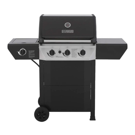
3-BURNER gRILL wITH SIDE BURNER
Purchase Date _________________________
1
ITEM #0503217
MODEL #GD4215S
Español p. 38
Lowes.com/masterforge
®
Advertisement

Related Manuals for Master Forge GD4215S

Summary of Contents for Master Forge GD4215S
- Page 1 ITEM #0503217 3-BURNER gRILL wITH SIDE BURNER MODEL #GD4215S Master Forge & M Design is a registered ® Español p. 38 trademark of LF, LLC. All rights reserved. wARNINg Improper installation, adjustment, alteration, service or maintenance can cause injury or property damage.
-
Page 2: Table Of Contents
TABLE OF CONTENTS Safety Information ......... . . 3 Package Contents . -
Page 3: Safety Information
SAFETY INFORMATION Please read and understand this entire manual before attempting to assemble, operate or install the product. If you have any questions regarding the product, please call customer service at 1-800-963-0211, 8:00 am to 6:00 pm, EST, Monday- Thursday, 8:00 a.m. - Page 4 SAFETY INFORMATION • Do not store a spare LP-gas cylinder under or near this appliance. • Never fill the cylinder beyond 80 percent full. • The regulator and hose assembly must be routed through the left leg assembly. Regulator must be locked with regulator hose lock before connected with LP tank. See page 18 for detailed assembly instructions.
-
Page 5: Package Contents
PACkAgE CONTENTS Lowes.com/masterforge ®... - Page 6 PACkAgE CONTENTS PART DESCRIPTION QUANTITY PART DESCRIPTION QUANTITY Firebox and Hood Knob Assembly Cooking Grate Regulator Hose Lock Heat Tent Left Leg Assembly Side Burner Right Leg Assembly Side Burner Grid Cart Leg Mat Warming Rack Diagonal Bar Barrier Right Side Table Bottom Panel Left Side Burner Table 1 Wheel Shaft...
-
Page 7: Hardware Contents
HARDwARE CONTENTS Axle Spacer M6 Nut Small Wrench Axle Washer R Pin Qty. 1 Qty. 1 Qty. 1 Qty. 1 Qty. 4 M6 x 12 M4 x 8 Wing Nut Screw Lock Washer Spring Washer Screw Qty. 1 Qty. 12 Qty. -
Page 8: Assembly Instructions
ASSEMBLY INSTRUCTIONS 1. Install gas cylinder safety stop Put the gas cylinder safety stop (V) into the holes of the bottom panel (S), then turn over the bottom panel (S) and insert 2 R pins (EE) into the small holes of gas cylinder safety stop (V). - Page 9 ASSEMBLY INSTRUCTIONS 3. Install left leg assembly Install left leg assembly (O) into bottom panel (S) with M6 x 12 screws (FF) and M6 lock washers (GG). Hardware Used M6 x 12 Screw Lock Washer 4. Install right leg assembly Install right leg assembly (P) into bottom panel (S) with M6 x 12 screws (FF) and M6 lock washers...
- Page 10 ASSEMBLY INSTRUCTIONS 5. Install front panels Align the two front panels (W) to preinstalled screws on front legs of cart. Slide the front panels (W) into place and tighten all 8 screws . Note: The front panel with the labels should be placed at the top of the cart.
- Page 11 ASSEMBLY INSTRUCTIONS 7. Install cart leg mat Install two cart leg mats (Q) into the legs of right leg assembly (P) with a soft hammer. 8. Install wheel Slip wheel (U) and axle spacer (AA) onto the wheel shaft (T). Then insert the wheel shaft (T) into the hole on legs of left leg assembly (O).
- Page 12 ASSEMBLY INSTRUCTIONS 9. Install firebox and hood assembly Set firebox and hood assembly (A) onto cart. Align the 4 pre-drilled holes in bottom of firebox and hood assembly (A) to the pre-drilled holes in the top of the cart assembly. Using 4 M6 x 12 screws (FF), 4 M6 lock washers (GG) and 4 M6 spring washers (HH), secure firebox and...
- Page 13 ASSEMBLY INSTRUCTIONS 11. Install right side table Align right side table (G) with the pre-installed screws of firebox and hood assembly (A). Slide the right side table (G) into place and then tighten the screws with screwdriver. 12. Install left side burner table Align left side burner table (H) with the pre-installed screws of firebox and hood assembly (A).
- Page 14 ASSEMBLY INSTRUCTIONS 13. Install side burner valve and knob bezel Put the side burner valve stem into the big hole on the front panel of left side burner table (H). Insert the knob bezel (I) into the side burner valve stem. Align the holes of knob bezel (I) and the holes of side burner valve.
- Page 15 ASSEMBLY INSTRUCTIONS 15. Check the distance between the ignition pin and the burner ports If the distance between the ignition pin and the burner ports is not the same as illustrated, loosen the ignition pin screws, adjust the distance and then re-tighten the screws.
- Page 16 ASSEMBLY INSTRUCTIONS 18. Install cooking grates Place cooking grates (B) onto firebox and hood assembly (A). 19. Install warming rack Place warming rack (F) onto firebox and hood assembly (A). Insert the legs of warming rack (F) into the holes of firebox and hood assembly (A).
- Page 17 ASSEMBLY INSTRUCTIONS 21. Install drip tray Slide drip tray (K) into drip tray brackets (J) underneath firebox and hood assembly (A). 22. Install grease cup Slide grease cup (L) into brackets at the bottom of drip tray (K). Lowes.com/masterforge ®...
- Page 18 ASSEMBLY INSTRUCTIONS 23. Install regulator hose lock Hoop the regulator hose into the regulator hose lock (N). Align the holes of regulator hose lock with the hole on the back of front leg of left leg assembly (O). Tighten the regulator lock with M4 x 12 screw (KK).
- Page 19 ASSEMBLY INSTRUCTIONS 25. Install gas tank Place a 20 lb. LP tank (not included) into round opening in the bottom of cart. Secure tank using gas cylinder safety stop (V). Connect regulator to tank and tighten by hand. INCORRECT REgULATOR ASSEMBLY The regulator and hose should not be routed through the gap between the bottom of firebox and the top of cart.
-
Page 20: Installation Instructions
INSTALLATION INSTRUCTIONS For Portable LP-gas Connection The cart has an opening in the bottom panel that allows a 20 lb.gas tank bottom flange to drop into place (tank not included).This will help to lock the tank in place. After positioning the tank in the opening, lift up the gas cylinder safety stop to lock the tank (Fig.
Need help?
Do you have a question about the GD4215S and is the answer not in the manual?
Questions and answers